Well, to help with an example is say the 148GTL...
When you go to a constant source for the Clarifier - I only worry about "center slot" - being that most people won't notice, or care - about the slide being greater - they just want to talk to their friends.
The easier you make the conversion - the less hassle the issue of slide becomes - for most won't use the extremes for the issues of stability are MAGNIFIED on both sides of the center slot - on any potentiometer.
The main idea here is as you work thru your conversion - if you keep the values, all the same - the only thing you may need to do later is tweak the coil for the mode to help bring the clarifier back to center slot - if any adjustment is needed.
Here's a thread I found from another user that might help shed some light on the issues I speak of, one being that most of the time - people change the external control "range" by changing or removing parts which gets you into trouble with case and chassis and parts getting clipped out or removed and the radio is never quite right until all the mods are removed - stock values brought in and soldered - then the PROPER rework needed by the customer simply wanting an "unlocked clarifier" but not all the slide or hassles with drift.
How do you solve for that? Simple - just remove RX and TX voltage - and just source the 8 V the PLL uses and send it to the Clarifier (Voice Lock)
Read this to help you
I have a old beat 148 GTL that someone many moons ago unlocked the clarifier. I can align AM and LSB but USB bottoms out. Will changing the value of R236 8200 ohm give me more adjustment? Probably one of Andys little graphics would help From what I see this is the only resistor that goes to...

www.worldwidedx.com
Another...
I am getting back into the CB world again. Back in the 70's I did alot of playing around with a GE AM/SSB unit with a 50w Polamar amp. The GE radio is gone but I still have the amp. I now have a Cobra 148 GTL sside 5 pin mike. I have made the modification to the receiver for increase rf...
www.worldwidedx.com
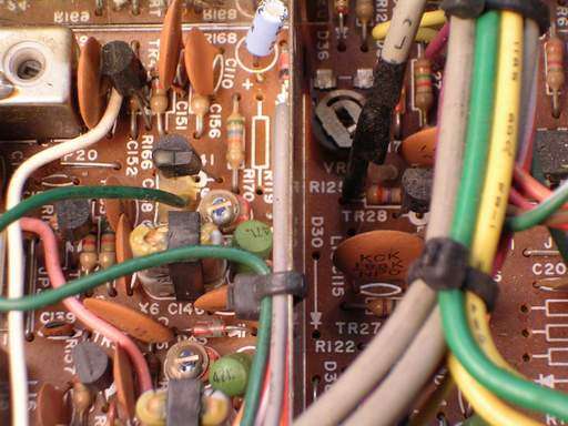
These deal with Cobras, but when you work with the TRC-458 - you'll see much of the discussion can apply to nearly any radio with a clarifier tied to a coil/crystal/cap tune design - simply by the source is varied by a pot set up a specific way to treat the varactor with SMALL changes in voltage.
It's how the voltage is applied in the circuit that the varactor is in, develops the IMPEDANCE load the varactor uses to tune its capacitive range with - you'll see various principles of swamping resistance and capacitance used on that clarifiers' line to the varactor - and how much of one affect how little or large that variance becomes against the tuning range.
Thats why your question is really two-fold - one being - doing the clarifier unlock procedure correctly and then tweaking the clarifier circuit to tune - and keep the clarifier's' "center-slot" so you can tune equally in both directions.
Don't worry, you're doing fine, I don't think we want to start throwing curveballs at you just yet until you're more comfortable with understanding how this game of clarifier unlocking works.