• You can now help support WorldwideDX when you shop on Amazon at no additional cost to you! Simply follow this Shop on Amazon link first and a portion of any purchase is sent to WorldwideDX to help with site costs.

Siltronics LA-550 " keying relay issues"

Danzik

Active Member
Oct 18, 2022
182
10
28
45
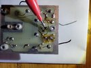
Well, I got the tubes all converted, installed and everything went very well there now on to the next issue I discovered, apparently the PO of the amplifier ran to many watts into the amp and or somthing else had happened as it looked like a lead on that little metal canister " what ever it is" was burnt completely away and there was also trace damage on the back of the circuit board coming from that component, what do you guys suggest I do to repair this, fix the original board or start over with another relay board like those on Ebay? I can tell someone else had done some previous soldering on this board 20221027_200940.jpgScreenshot_20221028-071816_Gallery.jpg
 

The canister is a transistor. I would check it, replace if necessary and clean up the traces/pcb.

SL
I can do if I can find the specs or data sheet for it to stick in the ohm meter, not sure which leads are the collector and emitter and what not but I bet it is destroyed anyways because the lead was actually blown right off of it I tried repairing it from a resistor lead i had, makes me wonder if anything else on that board is toast though to because I quickly fixed the trace and that transistor and it would still not key up, the relay itself is good as I tested it ‍♂️Screenshot_20221028-080517_Photos.jpg
 
No specs needed. if traces are burned, a junction in the device is shorted. Do a simple diode test, base to emitter, base to collector and collector to emitter. The schematic shows a 2N5814, but that is not what you are showing in your photo. It is not a critical part, it is just a switch that drives the relay coil. Any NPN ( 2N2222, 2N3904, etc) that will handle the current will work. I would also check D7, D8, Q1 and Q2 for good measure. You didn't say what part is used and it is hard to tell if it is a TO-5 or TO-39 package from the photo, but you should get a pinout of what is in there.
 
Last edited:
  • Like
Reactions: Danzik
No specs needed. if traces are burned, a junction in the device is shorted. Do a simple diode test, base to emitter, base to collector and collector to emitter. The schematic shows a 2N5814, but that is not what you are showing in your photo. It is not a critical part, it is just a switch that drives the relay coil. Any NPN ( 2N2222, 2N3904, etc) that will handle the current will work. I would also check D7, D8, Q1 and Q2 for good measure. You didn't say what part is used and it is hard to tell if it is a TO-5 or TO-39 package from the photo, but you should get a pinout of what is in there.
I sure will and thank you for the advice
 
One of the 3 leads is tied to the case. Perhaps that is the one that is missing? What is the part number of the device?
I will look when I get home as I am at work right now, I will have to look with a magnifying glass as the print is so small but it is the very top lead there in the photo that got burned away
 
No specs needed. if traces are burned, a junction in the device is shorted. Do a simple diode test, base to emitter, base to collector and collector to emitter. The schematic shows a 2N5814, but that is not what you are showing in your photo. It is not a critical part, it is just a switch that drives the relay coil. Any NPN ( 2N2222, 2N3904, etc) that will handle the current will work. I would also check D7, D8, Q1 and Q2 for good measure. You didn't say what part is used and it is hard to tell if it is a TO-5 or TO-39 package from the photo, but you should get a pinout of what is in there.
The 2n5814 may also be on the board I know there is one of those black plastic flat faced ones on there too
 
The 2n5814 may also be on the board I know there is one of those black plastic flat faced ones on there too
Then I am going to guess, that the 5814 was replaced with what you have now. I would remove it and test it and most likely replace it, since a lead is missing anyway.
 
Then I am going to guess, that the 5814 was replaced with what you have now. I would remove it and test it and most likely replace it, since a lead is missing anyway.
I will do whatever you tell me I should do as I would love to have this unit fixed, I lack in my electronics knowledge but with guidance I can and am willing to do it I will get back with better photos and part numbers here in a couple hours thank you
 
Then I am going to guess, that the 5814 was replaced with what you have now. I would remove it and test it and most likely replace it, since a lead is missing anyway.
Yes, I see exactly what you mean now, the schematic has 2 2N5814, I didn't even notice that until you mentioned it ! I am not the best at reading them
 
One of the 3 leads is tied to the case. Perhaps that is the one that is missing? What is the part number of the device?
The part # on that metal transistor is 2N3053 you can tell someone has messed with both transistors on the back of the board from the flux stains, I did have a temporary fix on that broken trace I am pointing at until I removed that transistor, I did a continuity test on all 3 legs and didn't have continuity on any of them, I did the same on the 2N5814 and did have continuity on 2 of the legs but it is still in the board, should I remove it and test it also ? I also have some 2nC945 transistors laying around here would those work as a replacement? Thanks 20221028_134656.jpg
 

Attachments

  • 20221028_134720.jpg
    20221028_134720.jpg
    1.4 MB · Views: 54
Also, should the zener diode which is currently installed have continuity because it does not, if any of the components need to be removed to test I sure will do so ! Thanks
 
Also, the component board # is 038 070 I don't know if you were asking that for that number earlier or the metal transistor
 
The part # on that metal transistor is 2N3053 you can tell someone has messed with both transistors on the back of the board from the flux stains, I did have a temporary fix on that broken trace I am pointing at until I removed that transistor, I did a continuity test on all 3 legs and didn't have continuity on any of them, I did the same on the 2N5814 and did have continuity on 2 of the legs but it is still in the board, should I remove it and test it also ? I also have some 2nC945 transistors laying around here would those work as a replacement? Thanks View attachment 61049
You need to use diode test mode, to properly bias the device. Continuity test is not valid. You should have around .6 volts forward from B-C and B-E in one direction. Reverse should be zero volts. C-E might have some leakage normally, might not. It depends of the device. I would remove both. clean the board, repair the burned/missing traces first. The 2SC945 is not a drop in replacement. Electrically it is similar. However, you will need to reverse the base and collector. With the flat side of the device facing you, The pinout of the 2N5419 is EBC. The 2SC945 is ECB.
 
  • Like
Reactions: Danzik

dxChat
Help Users
  • No one is chatting at the moment.