You need to use diode test mode, to properly bias the device. Continuity test is not valid. You should have around .6 volts forward from B-C and B-E in one direction. Reverse should be zero volts. C-E might have some leakage normally, might not. It depends of the
I got the transistors replaced and it is still not engaging unfortunately, is there a way to test one of the wires sending the signal to the relay or something I can check there ?You need to use diode test mode, to properly bias the device. Continuity test is not valid. You should have around .6 volts forward from B-C and B-E in one direction. Reverse should be zero volts. C-E might have some leakage normally, might not. It depends of the device. I would remove both. clean the board, repair the burned/missing traces first. The 2SC945 is not a drop in replacement. Electrically it is similar. However, you will need to reverse the base and collector. With the flat side of the device facing you, The pinout of the 2N5419 is EBC. The 2SC945 is ECB.
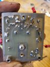
Hi, I have been working on this quit a bit trying to figure out what is going on with it, there is a green and yellow wire that runs to the bypass, low, and high power switch and it shows in the schematic that this wire should have 16v and it has hardly anything at all, I also check the 250 uf 20v capacitor and I am not getting anything there either, could the diode coming from the yellow power supply wire be bad or ??? There is also a red white and purple wire on that lug that goes down to this little transformer on the bottom here but I am only getting a gound on it also, it seems everything on that lug is showing a Gnd when it should be 16 VDCThe canister is a transistor. I would check it, replace if necessary and clean up the traces/pcb.
SL