
You are using an out of date browser. It may not display this or other websites correctly.
You should upgrade or use an alternative browser.
You should upgrade or use an alternative browser.
-
You can now help support WorldwideDX when you shop on Amazon at no additional cost to you! Simply follow this Shop on Amazon link first and a portion of any purchase is sent to WorldwideDX to help with site costs.
-
A Winner has been chosen for the 2026 July 4th Retevis RA89R Giveaway! Click Here to see who won!
strange o-scope probe. what is he referring to here?
- Thread starter loosecannon
- Start date
like a wall wart that is 6 volts?Nope! it won't work. You need an AC voltage to get the patterns.
It needs AC voltage. If the wall wart will only put out 6 Volts AC.
To test the P/N junctions of diodes or transistors IT HAS to be AC.
To test the P/N junctions of diodes or transistors IT HAS to be AC.
Cool to see this tool getting mentioned again.
About 43 years ago my boss introduced me to this trick. Called it the "octopus". He didn't know how it got that name. Said it was a Navy thing, used when he was assigned to run a lower-echelon radio-repair depot in the Marines.
Tells you right there how long ago that was. They don't fix their own broken stuff any more. Just send it back to the contractor and pull a spare unit off the shelf.
There have been a lot of variations out there. A company called Huntron sold one they called the Tracker. If you substitute a variable-frequency AC source you can read smaller capacitors and inductors than a 60-Hz drive signal allows. Their stuff had variable amplitude and frequency drive.
We had a Tenma brand 'scope years ago that had this feature built in. It used a drive signal around 12 Volts peak-to-peak. Allowed you to see both sides of a zener diode's response. But it worried me that some really low-power devices could be damaged by it.
Heathkit sold one built into a console with two 40-pin chip sockets and a 40-position selector switch. It would display the behavior of each pin on an integrated circuit, one by one.
Not so revealing by itself, but that's where the two chip sockets come into play. The idea was to plug a known-good chip into one socket and the chip under test into the other socket. Presumably a pin that behaves differently on the chip under test would reveal a fault. Called it their "signature analysis" tool.
Best part was that your 'scope had two traces displayed on it, one from each socket. The reference chip was a solid trace. The chip under test was intensity-modulated and showed up as a dotted-line trace. So long as they were identical, you didn't see the dotted lines, since the two traces would be perfectly superimposed on the scope's CRT. One by one if all the chip's pins responded identically it was probably good.
Gotta look that one up some day. Couldn't afford it at the time. We just used a known-good board to test a suspect chip, or a good chip to test a board for problems. Or (gasp) a 'scope to look for troubles that way.
Bought a large-screen 'scope at the Dayton flea market years ago to use for this purpose. Got really fond of being able to see it clearly from anywhere in the room.
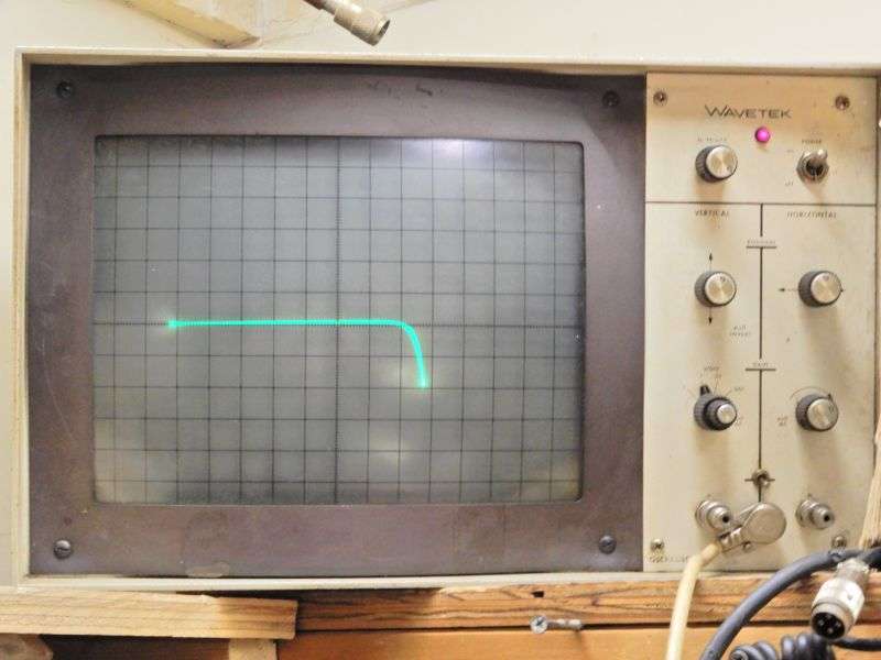
The Wavetek 1601 was meant to display frequency response attached to one of their sweep generators 40 years ago.
It has a blanking feature and stays dark so long as only a horizontal line is present. Turns on the trace so long as there is some vertical deflection. Keeps it from burning that horizontal line into the CRT's phosphor.
One of the most-important uses we have for this trick is to hook it to the cathode and grid of a 3-500Z tube. A loose grid wire will short only when it heats up enough to 'curl' and bridge the grid-to-cathode gap. A continuity test will show nothing from a cold tube out of the amplifier. We turn the tube on its side, rotate it and (gently) slap it on the side. A broken weld on a grid wire will allow it to make that grid-to-cathode short long enough to see on the CRT. The blanking feature is helpful here. If the trace flashes on at all, that tube is a time bomb. Not safe to put into a customer's amplifier.
No telling how many dollars' worth of amplifier damage we have prevented this way.
Good thing I picked up spares when I stumbled across them over the years. After about 10 years of running all day the CRT got dim on the one we were using. The spare is on that shelf above the bench now. Need to shop for a new CRT that fits it. Might be a real bug hunt.
73
About 43 years ago my boss introduced me to this trick. Called it the "octopus". He didn't know how it got that name. Said it was a Navy thing, used when he was assigned to run a lower-echelon radio-repair depot in the Marines.
Tells you right there how long ago that was. They don't fix their own broken stuff any more. Just send it back to the contractor and pull a spare unit off the shelf.
There have been a lot of variations out there. A company called Huntron sold one they called the Tracker. If you substitute a variable-frequency AC source you can read smaller capacitors and inductors than a 60-Hz drive signal allows. Their stuff had variable amplitude and frequency drive.
We had a Tenma brand 'scope years ago that had this feature built in. It used a drive signal around 12 Volts peak-to-peak. Allowed you to see both sides of a zener diode's response. But it worried me that some really low-power devices could be damaged by it.
Heathkit sold one built into a console with two 40-pin chip sockets and a 40-position selector switch. It would display the behavior of each pin on an integrated circuit, one by one.
Not so revealing by itself, but that's where the two chip sockets come into play. The idea was to plug a known-good chip into one socket and the chip under test into the other socket. Presumably a pin that behaves differently on the chip under test would reveal a fault. Called it their "signature analysis" tool.
Best part was that your 'scope had two traces displayed on it, one from each socket. The reference chip was a solid trace. The chip under test was intensity-modulated and showed up as a dotted-line trace. So long as they were identical, you didn't see the dotted lines, since the two traces would be perfectly superimposed on the scope's CRT. One by one if all the chip's pins responded identically it was probably good.
Gotta look that one up some day. Couldn't afford it at the time. We just used a known-good board to test a suspect chip, or a good chip to test a board for problems. Or (gasp) a 'scope to look for troubles that way.
Bought a large-screen 'scope at the Dayton flea market years ago to use for this purpose. Got really fond of being able to see it clearly from anywhere in the room.
The Wavetek 1601 was meant to display frequency response attached to one of their sweep generators 40 years ago.
It has a blanking feature and stays dark so long as only a horizontal line is present. Turns on the trace so long as there is some vertical deflection. Keeps it from burning that horizontal line into the CRT's phosphor.
One of the most-important uses we have for this trick is to hook it to the cathode and grid of a 3-500Z tube. A loose grid wire will short only when it heats up enough to 'curl' and bridge the grid-to-cathode gap. A continuity test will show nothing from a cold tube out of the amplifier. We turn the tube on its side, rotate it and (gently) slap it on the side. A broken weld on a grid wire will allow it to make that grid-to-cathode short long enough to see on the CRT. The blanking feature is helpful here. If the trace flashes on at all, that tube is a time bomb. Not safe to put into a customer's amplifier.
No telling how many dollars' worth of amplifier damage we have prevented this way.
Good thing I picked up spares when I stumbled across them over the years. After about 10 years of running all day the CRT got dim on the one we were using. The spare is on that shelf above the bench now. Need to shop for a new CRT that fits it. Might be a real bug hunt.
73

Geez, I remember these from way back. One of my final tech exams was 'identify the component in the box' using a similar device.
I just got a scope and I ordered one of these
https://www.ebay.com/itm/Dual-Range...ter-Tracker-/153031501208?txnId=1842640273005
.jpg")
https://www.ebay.com/itm/Dual-Range...ter-Tracker-/153031501208?txnId=1842640273005
dxChat
- No one is chatting at the moment.