• You can now help support WorldwideDX when you shop on Amazon at no additional cost to you! Simply follow this Shop on Amazon link first and a portion of any purchase is sent to WorldwideDX to help with site costs.

Turner +2 ssb mic pinout to HR-2510

Greetings all!,

New here so, if I screw-up a bit, bear with me till I get the hang of it.

About me:
In radio for 50 years, Amateur Extra Class License, VEC., 60' Rohn tower which had a full 20-meter beam (a monster 40'x30' approx.---avatar shows view from boom of beam) on it but, took down after the hurricanes here in Central Florida, couple of Dentron amps and Dentron tuner, Icom HF, Yaesu, Alinco, etc etc.

I have read this thread over and over.... I recently dusted off my equipment and dug out a Turner power desk mic (with switch on bottom, control on rear portion of base) and installed battery. This mic is a 4 wire mic, shield/braid - white - red - black....

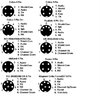
The radio is an HR-2510 10/11 meter mod which takes a 5 pin plug with not all pins being used. ....I have attempted to attach mic to plug to radio but, only can get it to key, but NO AUDIO.

Battery good,
element good,
mic contacts clean,
power mic control good,
no apparent broken wires,

As most of you know, the "freqs" can be moved up/down in this radio and I can do that by the simple shorting of pins....What the heck am I missing here as to why no audio?...I have horsed around with this quite a bit and getting frustrated, white to pin 1 of plug, braid/gnd to pin 2 and vice versa - UGH!.....

What am I missing here?..Thanks in advance.
 
Last edited:
***************************
Thanks for the reply.

So, what I still don't know is what wire goes where?.....
Audio is white (of course)...Pin #1 (no problem)

Shield/braid
is what it is of course....Pin #2 (no problem)

**Now there is the issue of pin #3...would that be the BLACK or red remaining wire?

What you are indicating is on the 4-wire mic cable, 3 of 4 wires are utilized, right?
 
RESULTS:

You gave me:
pin 1 audio - white
pin 2 - shield/common
pin 3 - tx (no color indicated)
Pin 4 - channel up
Pin 5 - channel down


***********************
I connected:

pin 1 - audio - WHITE

pin 2 - shield/common
pin 3 - tx - RED automatically keys
radio with bottom switch in
one of the two positions and
no audio.

Pin 4 - channel up - not using
Pin 5 - channel down - not using

*********************
I connected:


pin 1 - audio - WHITE

pin 2 - SHIELD/COMMON
pin 3 - tx - RED - automatically keys
radio with bottom switch in
one of the two positions and
no audio------then, connected
black wire to shield - same.

Pin 4 - channel up - not using
Pin 5 - channel down - not using
 
********************************

Thanks again for the reply -

HOWEVER, the President HR2510 is not listed, see pict.
View attachment 42646
***********************

Another update -

Connecting wires as in the picture attached above -
The radio will start scanning automatically unless I manually key it down which will cause it then to stop scanning and, still no audio (I did not install a 4.7 k resistor in white audio wire.)
 
ok here goes,,, 1. white (audio)
2. shield and red (gr. & rx)
3. black (tx)
4. NC
5. NC
Switch on bottow- E


oh and where are ya in central hot and sweaty or rainy and flooded state?
 
ok here goes,,, 1. white (audio)
2. shield and red (gr. & rx)
3. black (tx)
4. NC
5. NC
Switch on bottow- E


oh and where are ya in central hot and sweaty or rainy and flooded state?

************************
Thanks for the reply

ok here goes
1. white (audio) (No problem)

2. shield and red (gr. & rx) (No problem but 2 wires on one pin??

3. black (tx) (No problem)
4. NC
5. NC
Switch on bottow- E (No problem)


oh and where are ya in central hot and sweaty or rainy and flooded state?
Just a bit North of Orlando---and I hate it here. From Buffalo, New York. Easier to stay warm in Buffalo then to keep cool down here!
 
Last edited:
  • Like
Reactions: midnight special
************************
Thanks for the reply

ok here goes
1. white (audio) (No problem)

2. shield and red (gr. & rx) (No problem but 2 wires on one pin??

3. black (tx) (No problem)
4. NC
5. NC
Switch on bottow- E (No problem)


oh and where are ya in central hot and sweaty or rainy and flooded state?
Just a bit North of Orlando---and I hate it here. From Buffalo, New York. Easier to stay warm in Buffalo then to keep cool down here!

Below is how far I have gotten putting my "Radio room" back together....Daunting....

View attachment 42655
i am over in the plant city area,, on channel 1 or 19 usually every night til 2am,,,
 
"MS",
Look at my above post again please....Are you stating that pin # 2. shield and red have 2 wires on one pin?? (Will be back after a bit...).

view looking up.jpg
 
Last edited:
This is a pretty simple microphone scheme. If the wiring diagram technicoloco posted above is correct (and I have no reason to think that it isn't) you only need 3 wires from the Turner +2 to make it work on your 2510. (If the radio will receive with no mike plugged in, this is indeed the case.)

Per technicolo's info:
Pin 1 = Audio lead-White from the +2
Pin 2 = Shield or Common-Usually the braided "sleeve" over the white wire
Pin 3 = TX-Black wire from the +2

If the mike cable is not original to the Turner, all bets are off. If it has been changed, look at the diagram below of the bottom of the Turner and substitute the wire colors on the base of your example to the mike pins listed above.
InkedIMG_0198_LI.jpg

You should not need the Red wire-Yellow arrow above- (or whatever color if the cord is not original)connected at the base of the mike to make it work on the 2510.

The end of the movable leaf -Red arrow above-should have the Braid attached.

The end of the fixed/non-movable leaf of the switch-Blue arrow above-will be the Transmit wire. Originally a black wire but if not the original cord??????

The end of the fixed/non-movable leaf of the switch-Orange arrow above-will be the positive wire from the microphone element. This grounds the output of the element during receive.

Double check the action of all the leafs in the base of the microphone. It is pretty common for them to get bent out of shape after years of use. The orange leaf should "open" last so that there is no audio output until the unit is in transmit.

73
David
 
This is a pretty simple microphone scheme. If the wiring diagram technicoloco posted above is correct (and I have no reason to think that it isn't) you only need 3 wires from the Turner +2 to make it work on your 2510. (If the radio will receive with no mike plugged in, this is indeed the case.)

Per technicolo's info:
Pin 1 = Audio lead-White from the +2
Pin 2 = Shield or Common-Usually the braided "sleeve" over the white wire
Pin 3 = TX-Black wire from the +2

If the mike cable is not original to the Turner, all bets are off. If it has been changed, look at the diagram below of the bottom of the Turner and substitute the wire colors on the base of your example to the mike pins listed above.
View attachment 42662

You should not need the Red wire-Yellow arrow above- (or whatever color if the cord is not original)connected at the base of the mike to make it work on the 2510.

The end of the movable leaf -Red arrow above-should have the Braid attached.

The end of the fixed/non-movable leaf of the switch-Blue arrow above-will be the Transmit wire. Originally a black wire but if not the original cord??????

The end of the fixed/non-movable leaf of the switch-Orange arrow above-will be the positive wire from the microphone element. This grounds the output of the element during receive.

Double check the action of all the leafs in the base of the microphone. It is pretty common for them to get bent out of shape after years of use. The orange leaf should "open" last so that there is no audio output until the unit is in transmit.

73
David
************************************
Thanks for the reply

If the mike cable is not original to the Turner, all bets are off. If it has been changed, look at the diagram below of the bottom of the Turner and substitute the wire colors on the base of your example to the mike pins listed above.
as stated. mic cable is orig

Double check the action of all the leafs in the base of the microphone.
was 2nd thing i did and all is well

It is pretty common for them to get bent out of shape after years of use.
agreed

The orange leaf should "open" last so that there is no audio output until the unit is in transmit.
will attempt (or should I say "re-attempt" based on what you have written...I will return.
 

dxChat
Help Users
  • No one is chatting at the moment.
  • @ Wildcat27:
    Hello I have a old school 2950 receives great on all modes and transmits great on AM but no transmit on SSB. Does anyone have any idea?
  • @ ButtFuzz:
    Good evening from Sunny Salem! What’s shaking?
  • dxBot:
    63Sprint has left the room.