• You can now help support WorldwideDX when you shop on Amazon at no additional cost to you! Simply follow this Shop on Amazon link first and a portion of any purchase is sent to WorldwideDX to help with site costs.

Turner Mics a No-go with New Anytone 5555n ii !!!

moonrakercat

New Member
Jan 19, 2024
14
7
3
57
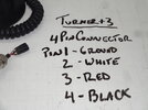
So I upgraded from a quad 6 to a new quad 5n2. I made an RJ45 to 4 pin adapter cable for the new radio - and wanted to use my favorite mic on the new radio - my Turner +3. I have used my turner +3 on my quad 6 fine- I love it. (also with an adapter cable I made)

Well all my other mics, realistic power mic, d104 mic - work fine with the 4 pin / RJ45 adapter cable for the new radio - but not the turner +3. I even tried a turner +2 - and same - no go.

When the turners are hooked up and I press the talk button nothing happens on the radio - it just receives....and when I flip the bottom switch on the turner the radio goes into transmit mode (without pressing the talk button on the mic) - but no modulation - when I press the talk button the radio goes into receive - weird.

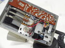
I know turners are different than standard mics. I checked the white wire in the mic cord in the base of the mic- it has an electrolytic cap on it - I removed it and put in a 104 cap - but it makes no difference. Neither does switching the radio between dynamic & electret.

I have double & triple checked the adapter cable rj45 to 4 pin that I made - with the stryker reference diagram on the net - and am 99 % sure my wiring is fine.

Anyone have any suggestions ??? Anyone else seen this issue with the new anytone ?? Anyone else tried a turner +2 /+3 on the new quad 5 ???? I'd love to get my turner +3 working with my new radio - but so far no luck - and I don't know why.
 

This is the way I wired my adapter. I thought it might be my wiring but my d104 and realistic power mic work fine - can anyone confirm if this is wrong ???
adapter.jpg
 
  • Like
Reactions: jrd426
Hi Moonrakercat, can you show us a diagram or picture of the wiring in the base of the Turner +3 you are trying to make work ? There are many ways those can be wired and that is likely where the problem is.
 
  • Like
Reactions: moonrakercat
Hi Moonrakercat, can you show us a diagram or picture of the wiring in the base of the Turner +3 you are trying to make work ? There are many ways those can be wired and that is likely where the problem is.
Interesting - I did not know that - I'll take a pic & post it later - appreciate any help.
 
Hi Moonrakercat, can you show us a diagram or picture of the wiring in the base of the Turner +3 you are trying to make work ? There are many ways those can be wired and that is likely where the problem is.
Hi Coyote - here is a pic of the inside of the turner -- it does not look altered from stock - I'm having the same issue with both my turner +3 and +2 on the 5555n ii- my other 4 pin power mics (realistic & d104) work fine with the adapter I've wired like the above pic for the Stryker. Any help you can give is much appreciated

Matt
 

Attachments

  • DSC05365.JPG
    DSC05365.JPG
    177 KB · Views: 17
  • DSC05366.JPG
    DSC05366.JPG
    136.4 KB · Views: 17
It's very difficult to see what's going where in the picture. Would you be able to draw a simple diagram of the base wiring ? Just need to get a clear idea of how those three reed switches are wired and especially, how that switch on the bottom is wired into the circuit. On my +3 that bottom switch is not present and never was.
 
Ok - this issue has been solved -- my turner mics now work - two issues - on the 4 pin female connectors from the mics - two mic wires needed to be switched - the bare ground needed to be on pin 4 and the black wire needed to be on pin 1. (mine were backwards on both my turner mics)

Also - on the RJ45/4 pin connector cable above - I needed to disconnect the # blue wire to pin 4 completely - this cable only needs the 3 wires.

Thanks for all the input above guys !
???

On your drawing of the mic adapter, it says Cobra 4 pin.

If your Turner is using the stock internal wiring and the mic plug is wired for a Cobra 4 pin (or that is what you want it wired for), then pin 3 & 4 are backwards on the Turner mic plug.

Turner +3 4 pin mic plug wired for a Cobra 4 pin:
Pin 1 - bare copper stranded wire (Shield/Ground)
Pin 2 - White wire (Audio)
Pin 3 - Black wire (TX)
Pin 4 - Red wire (RX)
*Put the switch in the "electronic" mode on the Turner.

Mic adapter looks good - disconnect the Blue wire on your drawing.

Also the pin # on the RJ-45 is backwards. It is 8,7,6,5 not 1,2,3,4.


RJ-45 wiring:
Pin 8 = NC
Pin 7 = TX/Channels
Pin 6 = Audio
Pin 5 = Shield/Ground


In the Radio's Background Function menu #2, you can set the mic type to EL or DY. The default is DY (Dynamic). But, some people say that the audio sounds better using the EL (Electronic) type.

If you use "EL", Pin 6 will have ~5v DC on it to power an electret mic element.
You may want to add a .1 disc capacitor in series on the white wire in the Turner to block the DC voltage and keep it out of the Turner's amp section.
 
Last edited:
???

On your drawing of the mic adapter, it says Cobra 4 pin.

If your Turner is using the stock internal wiring and the mic plug is wired for a Cobra 4 pin (or that is what you want it wired for), then pin 3 & 4 are backwards on the Turner mic plug.

Turner +3 4 pin mic plug wired for a Cobra 4 pin:
Pin 1 - bare copper stranded wire (Shield/Ground)
Pin 2 - White wire (Audio)
Pin 3 - Black wire (TX)
Pin 4 - Red wire (RX)
*Put the switch in the "electronic" mode on the Turner.

Mic adapter looks good - disconnect the Blue wire on your drawing.

Also the pin # on the RJ-45 is backwards. It is 8,7,6,5 not 1,2,3,4.


RJ-45 wiring:
Pin 8 = NC
Pin 7 = TX/Channels
Pin 6 = Audio
Pin 5 = Shield/Ground


In the Radio's Background Function menu #2, you can set the mic type to EL or DY. The default is DY (Dynamic). But, some people say that the audio sounds better using the EL (Electronic) type.

If you use "EL", Pin 6 will have ~5v DC on it to power an electret mic element.
You may want to add a .1 disc capacitor in series on the white wire in the Turner to block the DC voltage and keep it out of the Turner's amp section.
Thanks Dr_Dx - that was my problem - my turner was not wired for the Cobra - once I rewired the plug - it now works fine on the 5555n ii. Funny how it worked fine on the quad 6 before - but not the new quad 5 - and now after rewiring the plug it still works fine on the quad 6. So the new quad 5 definitely needs a cobra wired mic setup.
 

dxChat
Help Users
  • No one is chatting at the moment.