• You can now help support WorldwideDX when you shop on Amazon at no additional cost to you! Simply follow this Shop on Amazon link first and a portion of any purchase is sent to WorldwideDX to help with site costs.

Turning an 827 into a Gainmaster style dipole

nav2010

Active Member
Sep 5, 2010
189
30
38
Thinking about turning my 827 into a dipole in the same arrangement of the Gainmaster but a few things are bothering me.
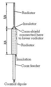
Firstly after reading what Shockwave says about the choke not being a rf choke but actually determining the length of the lower half of the dipole I can see some problems in my adaption.
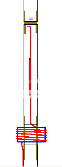
If I wind a choke around where my matching section used to be and run coax inside the lower 827 tube, there will be problems with attenuation and capacitance between the coax and the aluminium. I would have to isolate the top half of the dipole from the bottom which wouldn't be a problem and i could adjust the top half of the 827 to match the dipole arrangement.
The stub and the cap wouldn't be a problem but I can see problems running coax inside of the lower section.
Do you lot think that an aluminium lower section is impossible or could I get around it in some way.
 

NAV, isn't and 827 and all aluminum antenna? If I understand your idea, you basically plan to place the SGM's all wire type radiator inside of the 827 instead of using the fiberglass support structure like Sirio does, right?

Can you give us a reason for doing as you suggest? Do you really think that will work? It defies Nature, Physics and logic in my mind? The FG is, or at least should be, relatively transparent to the RF and current responses from the all wire radiator inside allowing it to radiate at some desirable angle, what are you thinking would go on inside if encased in all aluminum instead of the FG?

BTW, I think you need to talk to Bob85 on this forum, he recently posted his schematic and plans for just what you describe. He has all the details you'll need I'm sure. He is a man with a plan and leaves no stone unturned.
 
Can you give me a link to that thread Marconi?
See if this Bob bloke knows anything.

Here is an image he made using his EzBob software that he posted a while back and it describes almost to the T what you note above. I think he also suggested using an 827 here as well. It's here in this thread on page #18, post #172. I don't recall if there was much discussion about it however. Just post your questions here in this thread to Bob85. I haven't heard from Bob in a while, but if he's not working too much or is out of the country on business, maybe he'll get back to us.

827dipole1.png
 
Thanks for that. Out of the Country on business you say, sounds a real shady businessman or something.:D
 
The only problem I see with this schematic for the S-827 deals with the velocity factor in the lower section. For this to work, the velocity factor of the inside coax would need to be the same as the outside aluminum. Otherwise the coax and tubing length will be different. I'm not saying this idea will not work. I'm suggesting this variable will probably need to be addressed for proper tuning.
 
im still around eddie, just busy with other things, the 827 dipole was a brainwave i had, the details would have to be worked out and im not sure it would work;)
 
The only problem I see with this schematic for the S-827 deals with the velocity factor in the lower section. For this to work, the velocity factor of the inside coax would need to be the same as the outside aluminum. Otherwise the coax and tubing length will be different. I'm not saying this idea will not work. I'm suggesting this variable will probably need to be addressed for proper tuning.
From what I've read from your explanation of how the Gainmaster works Shockwave, if I decided to use the 827 as my lower section instead of using the coax then obviously I would need to isolate the base of the 827 so that it would be cut the correct length to represent the lower half of my dipole. Bearing this in mind, it would now probably need to be fed in the convensional way dipoles are fed which is with the coax 90 degrees to the elements to avoid interference.
This is not practical on antennae launched high up so I would consider running the coax on the inside of the tube or on the outside of the tube up to the feed point. A couple of points, firstly because i'm no longer using the coax as the lower half of the dipole then the rf choke which is on the Gainmaster probably wouldn't be needed on this antenna because that choke has the job of determining the lower section when its coax. If I did use a choke, would I create a double bottom element as such? My thoughts were the choke on my antenna would need to be right at the feedpoint so it would be better having the coax on the outside of the tube?
Velocity factors of different materials may not be an issue if I used this arrangement.
I will still need the matching stub and the cap to tune the antenna.
In your opinion Shockwave, if someone built a 5/8ths dipole out of aluminium, convensionally fed at 90 degrees to the feedpoint, with the coax running 90 degrees for at least a wave length, then matched it to 50 ohms, would it perform the same as a Gainmaster if they were both at the same height?
Or is there something special about the Gainmaster with its rf choke per se?
 
The only problem I see with this schematic for the S-827 deals with the velocity factor in the lower section. For this to work, the velocity factor of the inside coax would need to be the same as the outside aluminum. Otherwise the coax and tubing length will be different. I'm not saying this idea will not work. I'm suggesting this variable will probably need to be addressed for proper tuning.

If it would work SW, I can't figure out what the advantage or benefit would be. I have my doubts that it will work as intended however, but I've been wrong before.

Did you see my video report for my Imax vs. my GM I just posted above? The first time I ever saw a favorable report using my Imax. I'm going to test it a few more days, the old fashion way, recording signal reports on some of my regular local buddies. Problem is I've lost a couple and that will alter the results to some degree, so we'll see. Right now I see some reports favoring with the GM while others favor the Imax. I do tend to hear a little better with the GM most of the time.

I just talked with a guy in the Texas City, right across the Galveston Bay from Galveston Island where he lives. He was on the flat side trying a little DX up into the NorthEast and was surprised I heard him due North in Houston about 60-70 miles away on the North West side of the city. Tim switched to his Imax and the contact improved. I did hear him better on my Imax, but he said the GM sounded louder and better on his end.

I did video the contact and I might post it on YouTube if I find I described what was going on well enough to understand something regarding the antennas.

Since I started this recent series of comparisons, I was planning to finally do the Imax vs. the GM's, its most likely competitor, albeit the recent price increase from H & Y...which might just kill its sales.
 
If it would work SW, I can't figure out what the advantage or benefit would be. I have my doubts that it will work as intended however, but I've been wrong before.
There are several advantages Marconi. Firsly, the world is full of 827's that have gone open circuit. If they could be used for another purpose which might have more gain then it may be worth having a crack at.
Secondly, 827's are strong antennae and their integral strength is worth keeping minus the 8 elements which would make them even less vunerable to high winds. Another weak point is where the elements attach to the hub and if you can get rid of the need for them then that would be excellent.
If it can't be done then it can't be done but there is no harm in trying if you can get one to perform as good as a Gainmaster.
 
I have enough trouble getting CB vertical kits to work their best without trying to modify them using a somewhat revolutionary new design.

I've heard expert antenna whizzes of this forum and others say the SGM design is old hat, but I doubt that. It might be old theory as most stuff really is, but the application is new to me.

It's easy to talk, but I always encourage real efforts at something new in antenna design nav2010, so I look forward to your new project if you try it.

Keep us posted, OK?
 
I have enough trouble getting CB vertical kits to work their best without trying to modify them using a somewhat revolutionary new design.
I wouldn't say the Gainmaster is a revolutionary design, after all its a dipole, It has a few stages i've never seen before in a design.
Can't remember seeing a design that used a wire for the top half of the dipole and the feed coax choked off to provide the electrical length for the lower section of a dipole. Its not the first time dipoles have not been an half wave length long either, there are variants out there especially in UHF and VHF.
I am of course assuming that because it is longer than an half wave dipole then that is what gives it the extra gain.
 
The choke at the bottom of the GM decouples the feedline from the antenna in the same way as in any antenna application. If one removes the choke there will be considerable CMC on the feedline. As I understand it, in the case of the GM it does additionally define the antenna as opposed to the feedline, a line of demarcation, so to speak. I would think that would also hint to the necessity of remaining true to the original design, or else one is simply building a dipole. I have built 1/2ƛ dipoles where the feedline passed through the end of a pipe and fed at the center (see below. In the posted illustration there is a pipe over the entire coax going up from the bottom and the coax shield is attached at the top of the pipe. This is also done simply folding back the coax shield over the feedline.). They neither had nor needed a stub match or capacitor. I did use a coax choke at the point the the coax emerged from the end of the pipe.

Either a person is building a conventional "end fed" dipole, or he is building a GM copy. There has been a lot of discussion re the GM in an effort to discover whether it does the job advertised, and whether it exceeds the performance of previous 5/8ƛ antennas. Some of the discussion has been about the how and why of its design. To replicate one, I would think it would need to be a true copy or else the technological advantages reported for the model are not present even if it works. Dipoles work, but do not offer the gain reported for the GM.

Just my thoughts.

coxial.jpg
 
Dipoles work, but do not offer the gain reported for the GM.
Half wave dipoles won't give the same gain as a GM, the GM is a 5/8ths dipole.
I don't see anything special about the GM that would suggest that a different 5/8ths dipole couldn't match it. Electrically they would be very similar especially if you used the stub and cap tuning method.
 
I can't debate that. I just see that there are tests/comps being done and the GM is trending to better performance than other 5/8ƛ verticals. Perhaps what you propose to do will establish your point of view. It should be interesting, at least.
 
Last edited:

dxChat
Help Users
  • No one is chatting at the moment.
  • @ Wildcat27:
    Hello I have a old school 2950 receives great on all modes and transmits great on AM but no transmit on SSB. Does anyone have any idea?
  • @ ButtFuzz:
    Good evening from Sunny Salem! What’s shaking?
  • dxBot:
    63Sprint has left the room.
  • dxBot:
    kennyjames 0151 has left the room.