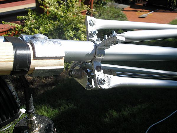
It should have read 85 feet, and, yes, the antenna is isolated. Today I added a wooden dowel - Ash shovel handle - between the antenna and the mast.
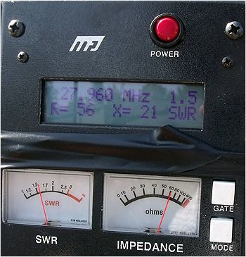
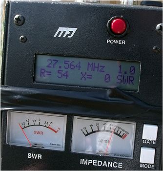
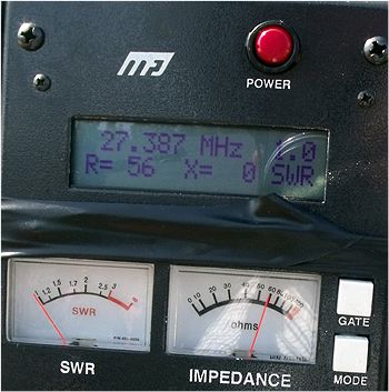
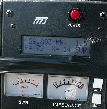
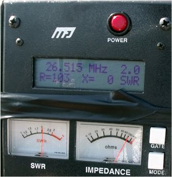
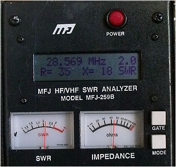
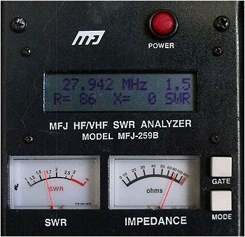
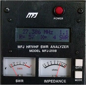
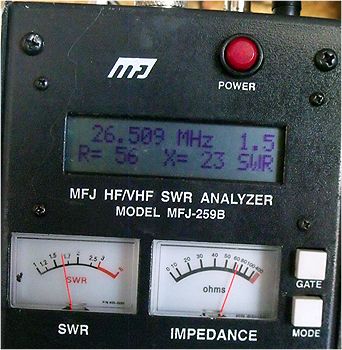
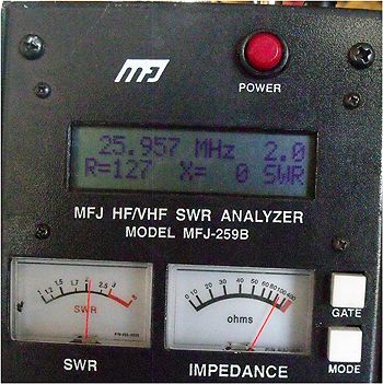
I also tested the coax with a dummy load. It had a 1.1 or 1.0 SWR with from R52/X0 to R50/X0 across the 27 Mhz spectrum.
The dummy load was the same on the electrical 1/2ƛ jumper.
What did this test using the dummy load suggest to you about what you're seeing with the antenna instead of the dummy load at the end of the line?
Do you see how much difference in resonance your antenna produces just changing the feed line length? If you don't get this issue under better control, and it doesn't have to be perfect like you dummy load shows, but you need better control or nothing else you do will produce predictable or good results unless you just get real lucky.
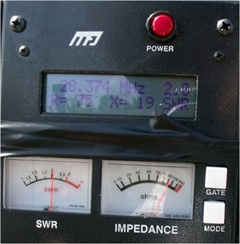
This is as a note only. My Sigma4 at 11' feet shows a resistive match over the following <2.0:1 SWR bandwidth range R=19 to R= 66, with a reactive match X=-6 to X=-23 for the full bandwidth. This data overall is much better than you are reporting.
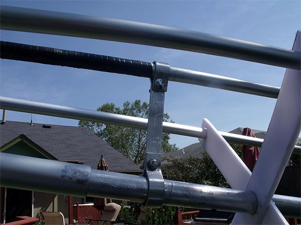
This data was read via my Autek VA1 connected directly to the feed point, but I don't have enough reports to establish a good trend of the match, because I was doing like you are, trying to test too many things at once and before I got a real good control over the match. I was just chasing my tail. At some point I also found a structural error in the angle for the gamma match. It was not centered precisely between the radials as it should be. That threw my resonance off and changing the reactive part of the antenna would not fix the problem because I had a bump in my matching device. This is also what I see in your gamma construction, an impedance bump that possibly shows unreliable results. I probably bumped the gamma out of position at some point over the years while stored in the garage.
There is good information on the New Vector 4000 manual that might help you get closer than you are now. First off, your bandwidth shows to be much wider than the model should produce. It is more than twice what Sirio shows for their similar antenna. It is nice to have a good wide bandwidth in some cases, but it can also be the result of increased losses somewhere...and then it is not so desirable. This often happens with a new antenna that has never been tested or tuned before, and then only if the maker does a lot of prep work, marking or fixing the dimensions to be used and then testing the results...will such an antenna work as predicted, right out of the box.
A long time ago I suggested to both you and Booty Monster to set your antennas up exactly as Sirio indicated in their manual for the New Vector 4000, don't add anything or modify anything. Purpose being to get you close to a working antenna that shows good results right out of the box...which I think the NV4 produced by Sirio does surprisingly well. When I say, "...shows good results right out of the box." I'm not talking about performance, I'm referring to some characteristic that the manufacture provides that can be easily measured by any CB'r. In this case it is the bandwidth which is a very good indicator that most CB operators can measure and chart easily.
Then Homer, when you're satisfied and not still wondering like you are now and noted in an earlier post, you could then start to experiment and have a reasonable base line for comparisons to check out your ideas.
This idea is not prefect, but without a measurable base line to start with, you will likely just be spinning your wheels with your modification ideas.
IMO your base line is the most important consideration for you right now, and without it to compare too, you are just guessing. You already know you need a good match, you can tell what that looks like using your analyzer, and your antenna shows a good SWR already, but the bandwidth you get is not similar to what the manufacture has suggested. Just like you are, I would question such results, both good and bad in this case.
Something just isn't quite right yet, and if your current match and bandwidth were closer to what I see with my S4, then I would say you have a good base line to start with, and then you can do your experiments with other ideas, like playing with a longer radiator, adding a balun, top hat or no, and isolation. Also try and remain consistent with the height you are working at during the process of testing.
Don't do like I did, constantly changing height around. Reason is now I don't always have reliable data in my files or antenna notes to compare fairly.
Good luck.

.jpg")
.jpg")


.jpg")
