LOL.that's some camera you have there homer, the first gamma strap looks longer than the latest revision.
Yes it does. The first was made of narrower, and thinner materials. It appears longer than this one.

LOL.that's some camera you have there homer, the first gamma strap looks longer than the latest revision.
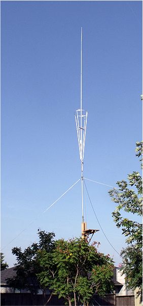

I couldn't resist pointing out that if the cone did not radiate, the gain Homer is seeing over a half wave dipole would not be possible. Without the cone, the Sigma is just an end fed 1/2 wave. With the cone it's a half wave over a 1/4 wave and phased constructively.
why wouldn't it be a 3/4 wavelength (+) vertical without the basket ? not that 3/4 would be better since FWIU beyond .64 WL the TOA starts being dominated by higher higher angled lobes .
and thanks for another excellent thread on this type of antenna . i'm looking forward to getting mine back up hopefully .
I couldn't resist pointing out that if the cone did not radiate, the gain Homer is seeing over a half wave dipole would not be possible. Without the cone, the Sigma is just an end fed 1/2 wave. With the cone it's a half wave over a 1/4 wave and phased constructively.
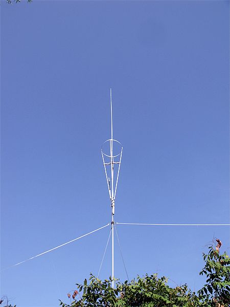
Donald would it be possible to show the cst plots of the old vector 5/8 over a 1/4 wave against the what i would imagine are similar plots of the 1/2 wave over a 1/4 wave new vector / sigma 4,
i'm curious to see what effect the extra 1/8 wave radiator had on the phasing and why sirio returned to the 1/2 over 1/4 wave format, i'm assuming it was to strengthen the antenna but i'm curious to know what the trade off was, it wouldn't surprise me if the new vector lost an insignificant amount of performance over the old vector in favour of stronger construction.

