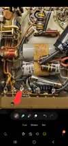
Hi guys I am about ready to pull my hair out over this modulator, last week it hot plated a tube popped a fuse so I went ahead and replaced the HV capacitors and the 100 uf 200vdc capacitor for the bias. When it first screwed up I put a voltmeter on pin 5 on the 8417 tube and watched the negative bias slowly go from -24 up to -19 then the tube plate started turning red, so I went ahead and started testing diodes and resistors on the bias rail there and couldn't really find anything at fault I went ahead and replaced the power diode, the zener diode with a 1W 36V and the resistors and now I am only getting around -5 volts on Pin 5 , I don't know what's going on does anyone have any suggestions???? This is a photo before I replaced the caps and such however I have -150 vdc right at the red slash mark then only -5 vdc after it on the rail. I have several of these units but my others are different versions, this one is the older 2 tuber and the bias ends up going through the relay but I am testing it before that point.

You are using an out of date browser. It may not display this or other websites correctly.
You should upgrade or use an alternative browser.
You should upgrade or use an alternative browser.
-
You can now help support WorldwideDX when you shop on Amazon at no additional cost to you! Simply follow this Shop on Amazon link first and a portion of any purchase is sent to WorldwideDX to help with site costs.
-
A Winner has been chosen for the 2026 July 4th Retevis RA89R Giveaway! Click Here to see who won!
Wawasee JB150 issues "low bias"
- Thread starter Danzik
- Start date
As a starting point I guess, does anyone know what I should have on this blue wire coming from the transformer? I am starting to wonder if the transformer doesn't have issues or somthing, since there were so many versions of the JB 150 it makes it hard with the schematics. Thanks


Work on it without the tube installed until you get the negative bias voltage correct at the tube socket. If you have -150 at the bias filter cap, it can only be an open 10k 1 watt resistor or, a short across the zener diode. The possibly of the short can be inside the zener or, the circuit it feeds, including the tubes control grid.
Another thing to consider is these units were sold as receiver pre amplifiers that required reversal of the wiring on the relay, to make it work on transmit. Sometimes the bias contacts were not properly wired or, even completely missing on models with two pole relays. Luckily, yours has 3 poles.
When it is correct, you should see something close to negative 120 volts on the tubes control grid pin in receive and around -36 volts when you push the relay in with an insulted rod.
If you find both the zener diode and the 10k, 1 watt resistor have burned up, it's a strong indication the control grid, shorted out to the screen grid, inside the tube. GE 8417 tubes can be prone to this, once overloaded to a red anode.
The JB amplifiers increase the chances of this type of internal tube arc or short, because they apply half of the plate voltage, to the tubes screen grid. Getting that down to between 150 and 200 volts using a 10k 10 watt dropping resistor feeding a 150 volt zener, buffered by an NPN output transistor, makes a big difference here. Using the zener across the base and collector of the NPN transistor, forms a powerful shunt screen regulator.
That stabilizes the screen voltage and tube gain during positive audio peaks and prevents negative screen current from increasing the voltage, that can cause the tube to overload and cherry the plate red.
Last edited:
I forgot to add, the blue wire you are questioning is the AC transformer secondary, for the bias voltage. It's feeding the diode half wave rectifier and filter cap. The side of the diode with the wire from the transformer, should show about 105 volts AC, to ground.
Thank you very much for your reply Shockwave, yeah the unit had ruined the tube completely so I am working on it now without a tube installed, weird thing is that I tried replacing the resistor, diode, zener diode without a change, I do know when it was on its way out I had -24 at pin5 on the tube and now I have about nothing, It is extremely possible the relay is wired wrong I believe, but first I just wanna see the negative bias back before messing with the relay. You say 10k resistor, I have replaced all 3 of these resistors, what is this one exactlyWork on it without the tube installed until you get the negative bias voltage correct at the tube socket. If you have -150 at the bias filter cap, it can only be an open 10k 1 watt resistor or, a short across the zener diode. The possibly of the short can be inside the zener or, the circuit it feeds, including the tubes control grid.
Another thing to consider is these units were sold as receiver pre amplifiers that required reversal of the wiring on the relay, to make it work on transmit. Sometimes the bias contacts were not properly wired or, even completely missing on models with two pole relays. Luckily, yours has 3 poles.
When it is correct, you should see something close to negative 120 volts on the tubes control grid pin in receive and around -36 volts when you push the relay in with an insulted rod.
If you find both the zener diode and the 10k, 1 watt resistor have burned up, it's a strong indication the control grid, shorted out to the screen grid, inside the tube. GE 8417 tubes can be prone to this, once overloaded to a red anode.
The JB amplifiers increase the chances of this type of internal tube arc or short, because they apply half of the plate voltage, to the tubes screen grid. Getting that down to between 150 and 200 volts using a 10k 10 watt dropping resistor feeding a 150 volt zener, buffered by an NPN output transistor, makes a big difference here. Using the zener across the base and collector of the NPN transistor, forms a powerful shunt screen regulator.
That stabilizes the screen voltage and tube gain during positive audio peaks and prevents negative screen current from increasing the voltage, that can cause the tube to overload and cherry the plate red.


I have also previously unsoldered the brown wires from the rail there to make sure there were not shorts farther down the circuit, but from my previous testing I believe they did not have the relay wired correctly from when it use to be a recieve booster probably like you mentioned because before I was only getting-24 vdc in standby so I bet it was and is backwards, so I will look at this more ! Thank you ShockwaveWork on it without the tube installed until you get the negative bias voltage correct at the tube socket. If you have -150 at the bias filter cap, it can only be an open 10k 1 watt resistor or, a short across the zener diode. The possibly of the short can be inside the zener or, the circuit it feeds, including the tubes control grid.
Another thing to consider is these units were sold as receiver pre amplifiers that required reversal of the wiring on the relay, to make it work on transmit. Sometimes the bias contacts were not properly wired or, even completely missing on models with two pole relays. Luckily, yours has 3 poles.
When it is correct, you should see something close to negative 120 volts on the tubes control grid pin in receive and around -36 volts when you push the relay in with an insulted rod.
If you find both the zener diode and the 10k, 1 watt resistor have burned up, it's a strong indication the control grid, shorted out to the screen grid, inside the tube. GE 8417 tubes can be prone to this, once overloaded to a red anode.
The JB amplifiers increase the chances of this type of the lineinternal tube arc or short, because they apply half of the plate voltage, to the tubes screen grid. Getting that down to between 150 and 200 volts using a 10k 10 watt dropping resistor feeding a 150 volt zener, buffered by an NPN output transistor, makes a big difference here. Using the zener across the base and collector of the NPN transistor, forms a powerful shunt screen regulator.
That stabilizes the screen voltage and tube gain during positive audio peaks and prevents negative screen current from increasing the voltage, that can cause the tube to overload and cherry the plate red.
Also, where is this 1w 10k resistor supposed to be that you speak of ???? I have not been going by the schematics since these boxes were made so many different ways I have just been going by what was already in it, I ran it a couple weeks before it went down and worked fine but I know that relay isn't wired correctly
Ok, I am going to try to break it down here and make it easier to understand what I have going on maybe, I disconnected the wire leads and those two resistors coming off the ground terminal and the anode of the zener. I have a -147 vdc here at the pointer 
 Here at the pointer in this location I only have -5 vdc at the anode of the zener, the zener is a new 1w 36v zener, is this correct or is the value of the large resistor wrong ? I think this is where the issue lies but why ? I get 23k ohms on that resistor with multimeter
Yeah, that's a fail. Should be 3300 ohms plus or minus 330 ohms.I get 23k ohms on that resistor
73
The resistor in question is supposed to be 22,000 ohms. At 23,000 ohms it's well within tolerance. I've also looked at another unit and it is the correct value. Your picture shows the only thing this resistor is feeding right now, is the diode with no other connections at that point and you were showing -5 volts at the junction between the resistor and the zener diode. The only way that's possible is if you have a 5 volt zener diode in that spot, or the 36 volt zener diode failed as a result of a tube short.View attachment 68372 Here at the pointer in this location I only have -5 vdc at the anode of the zener, the zener is a new 1w 36v zener, is this correct or is the value of the large resistor wrong ? I think this is where the issue lies but why ? I get 23k ohms on that resistor with multimeter
dxChat
- No one is chatting at the moment.