• You can now help support WorldwideDX when you shop on Amazon at no additional cost to you! Simply follow this Shop on Amazon link first and a portion of any purchase is sent to WorldwideDX to help with site costs.
  • A Winner has been selected for the 2025 Radioddity Cyber Monday giveaway! Click Here to see who won!

Wawasee JB-2000 issues

Danzik

Active Member
I Support WorldwideDX.com!
Oct 18, 2022
347
70
38
47
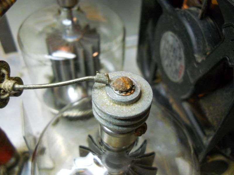
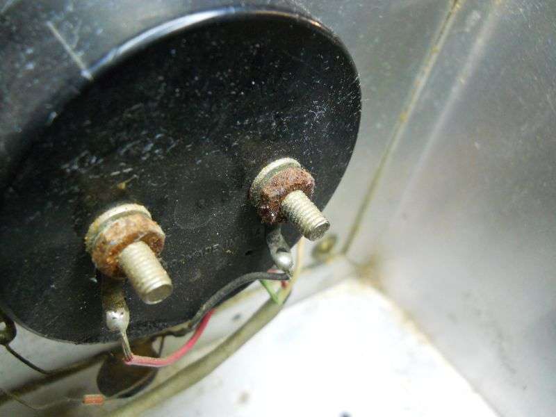
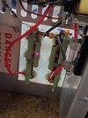
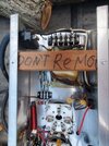
Hi all, I recently got ahold of this old JB 2000 and I am attempting to get er going and am having issues with it. Things I have replaced on it so far are HV caps, 3-500z tube sockets, and all the rectifier diodes. When I replaced the diodes all 4 on the side my finger is pointed at were all shorted, the other 4 tested good so I am guessing my problem is on this side ? I powered it up last night with no tubes installed, the HV delay clicked in fine and had over 2000 vdc to the plate section, but somthing just didn't seem right and seems I am smelling somthing hot but it is hard to tell with the fan running but I know some of the 39k 5 watt bleeder resistors are getting upwards of 200 degrees f. However it seemed ok then I heard a snap sound so I shut it down and knew it wasn't fixed and somthing else was up, so I let it bleed down and looked it all over and saw absolutely nothing. This unit still has the driver and I am kinda suspecting this board to be the possible suspect, the keying / driver board ? It has some old caps on this board but no continuity across the caps and my cheap 2 in one scope tester sees them as capacitors. The unit hasn't popped the 3amp fuse coming from the HV relay and it hasn't popped the breaker on the rear of the amp either. But somthing is popping, what about those door knob caps on the cap choke area ? The rear of the case says 10-80 but I haven't seen one like this so I am not sure that's the original cabinet and not sure the transformer is original either. Any info or recommendations would be greatly appreciated !!!! Thanks
 

Attachments

  • 20250630_164126.jpg
    20250630_164126.jpg
    1.7 MB · Views: 101
  • 20250630_164133.jpg
    20250630_164133.jpg
    1.1 MB · Views: 99
  • 20250630_164141.jpg
    20250630_164141.jpg
    934.7 KB · Views: 102
  • 20250630_164444.jpg
    20250630_164444.jpg
    1.1 MB · Views: 94
  • 20250630_202132.jpg
    20250630_202132.jpg
    2.2 MB · Views: 87
  • 20250630_202140.jpg
    20250630_202140.jpg
    1.8 MB · Views: 93
  • 20250630_202154.jpg
    20250630_202154.jpg
    1.9 MB · Views: 92
  • 20250630_202201.jpg
    20250630_202201.jpg
    1.9 MB · Views: 88
  • 20250630_202212.jpg
    20250630_202212.jpg
    2.2 MB · Views: 100
  • 20250630_202246.jpg
    20250630_202246.jpg
    2 MB · Views: 92
  • 20250630_202252.jpg
    20250630_202252.jpg
    2 MB · Views: 91
  • 20250630_202306.jpg
    20250630_202306.jpg
    1.7 MB · Views: 84
  • 20250630_202322.jpg
    20250630_202322.jpg
    2.1 MB · Views: 90
  • 20250630_202331.jpg
    20250630_202331.jpg
    2.1 MB · Views: 86
  • 20250630_202355.jpg
    20250630_202355.jpg
    1.8 MB · Views: 91

Also I may add that mine does not have the 10 watt 2 ohm resistor off of the 3 amp fuse holder to the HV capacitors either but think I will install one. Also, what is this 25 watt resistor I have circled, don't believe I have seen that in there ? Screenshot_20250701-100846_Drive.jpg
 
The only way we'll service that model is to convert it to high drive. The built-in driver tube is more bottle rocket than hot rod. The short service life wasn't a deal breaker 50 years ago when the 8417 was cheap. We found that the older that type tube got, the sooner they would fail in this amplifier. Makes using the internal driver a total waste of time and money. The circled resistor was to throttle down the driver tube just a bit. The 6CA7 or 8417 driver tubes were never meant to operate with more than 500 Volts on the plate circuit. The JB2000 runs the driver tube at 1200 to 1300 Volts. Like I said, more bottle rocket then drag racer.

Can't remember if we posted the conversion on this forum. Was a while back. We just replace the keying circuit with a new one. A small fan goes under the two tube sockets. Bolts to the flange edge of the front/rear divider rail. Without that, the sockets overheat. Matching the input impedance of the two Z tubes gets done with a small coil wound on half-inch diameter and two or three disc capacitors.

Just did a search on this forum. Didn't see the conversion info. I'll see what's in the archives at work later.

73
 
  • Like
Reactions: Danzik
The only way we'll service that model is to convert it to high drive. The built-in driver tube is more bottle rocket than hot rod. The short service life wasn't a deal breaker 50 years ago when the 8417 was cheap. We found that the older that type tube got, the sooner they would fail in this amplifier. Makes using the internal driver a total waste of time and money. The circled resistor was to throttle down the driver tube just a bit. The 6CA7 or 8417 driver tubes were never meant to operate with more than 500 Volts on the plate circuit. The JB2000 runs the driver tube at 1200 to 1300 Volts. Like I said, more bottle rocket then drag racer.

Can't remember if we posted the conversion on this forum. Was a while back. We just replace the keying circuit with a new one. A small fan goes under the two tube sockets. Bolts to the flange edge of the front/rear divider rail. Without that, the sockets overheat. Matching the input impedance of the two Z tubes gets done with a small coil wound on half-inch diameter and two or three disc capacitors.

Just did a search on this forum. Didn't see the conversion info. I'll see what's in the archives at work later.

73
Yeah, Nomad I toltally understand what you are saying here ! I would be very interested in the bypass conversion instructions if you could locate it . I am also planning on installing a fan for my new tube sockets also as I have read about the solder pins issues. I also wonder and am interested in if there is a way to add a second 8417 driver tube instead and split the plate voltage???? Is there a simple way to just add another tube so they don't have to work as hard to produce that 100 watts going into the finals ? Sounds like the JB 200 would be a perfect driver for that box though. Thanks also I have one of your keying circuits already and sounds like it may be going in this unit
 
The JB2000 walks a fine tightrope the way it's designed. The big tubes operate with zero bias. This has the effect of exaggerating the carrier level. This allows the driver tube to operate with the carrier held low enough to prevent immediate burnout of the driver tube. This also makes the Z tubes run hot, but that's the tradeoff.

Our routine high-drive conversion includes a zener diode to reduce the tubes' idle current. Really reduces the heat load from the AM carrier. But this would not be practical with a driver tube, since it would now have to produce more drive-carrier power. Making life easier on the Zs would make life short for the driver tube.

An old friend put a pair of 6LQ6 in his JB2000 in place of the 8417. Never did get it stable. Just wanted to oscillate. May have had more to do with his layout and bypassing than anything else. He gave up on it before I laid eyes on the amplifier. We installed a 4X150 driver tube in a JB once. Was a bit crowded in that front-right corner of the chassis. The tube requires a forced-air blower, made the form factor awkward. Never could make it stable. Just wanted to oscillate, even with shielding around the tube. Gave up on that. Chalked it up to "just because you can doesn't mean you should".

Customer traffic was busy today, didn't get the chance to dig for the conversion files. I'll have some slack time this weekend to pick that up where I left off.

73
 
  • Like
Reactions: Danzik

Not the detailed post I think I remember, but hits the highlights.

73
 
  • Like
Reactions: Danzik
The JB2000 walks a fine tightrope the way it's designed. The big tubes operate with zero bias. This has the effect of exaggerating the carrier level. This allows the driver tube to operate with the carrier held low enough to prevent immediate burnout of the driver tube. This also makes the Z tubes run hot, but that's the tradeoff.

Our routine high-drive conversion includes a zener diode to reduce the tubes' idle current. Really reduces the heat load from the AM carrier. But this would not be practical with a driver tube, since it would now have to produce more drive-carrier power. Making life easier on the Zs would make life short for the driver tube.

An old friend put a pair of 6LQ6 in his JB2000 in place of the 8417. Never did get it stable. Just wanted to oscillate. May have had more to do with his layout and bypassing than anything else. He gave up on it before I laid eyes on the amplifier. We installed a 4X150 driver tube in a JB once. Was a bit crowded in that front-right corner of the chassis. The tube requires a forced-air blower, made the form factor awkward. Never could make it stable. Just wanted to oscillate, even with shielding around the tube. Gave up on that. Chalked it up to "just because you can doesn't mean you should".

Customer traffic was busy today, didn't get the chance to dig for the conversion files. I'll have some slack time this weekend to pick that up where I left off.

73
I have been back to messing with this thing after leaving it on the bench for quite some time over the summer. If I can figure out what is going on with it I will probably continue with the driver bypass but would at least like to see it functional first. It was my understanding that running the unit on low bypassed the operation of the driver tube, couldn't I just run it that way and put more wattage into it to get my desired drive or will this just burn out the keying circuit and still hard on the driver tube anyways due to the higher plate voltage that would still be present????? Anyways,,,,,, I have been working on the amp lately and I basically rebuilt the whole driver board with new caps some resistors just to see if maybe that was causing a issue and I don't believe it was. I also replaced all 3 door knob caps on the plate HV. Now, I can power up the amplifier with all tubes in place as long as I do not have the plate HV on the 3-500z's, I hook that up and all deals off the tube or tubes will internally arch and the breaker on the rear of the amp trips ! I do not know for sure but I do not think the tubes are the cause I belive it is somthing else because the amp would act funny and click before without any tubes even in it but now after replacing so many parts its not doing that anymore! What if by chance it was that timer delay/ relay not wanting to hold under load would that perhaps lead to something like this ? It's hard to tell because of coarse when it is arching I am sure that high voltage relay is kicking in and out and the breaker probably is too so I am kinda at a loss here, usually it is the tube on the right that arches unless I pull the one on the right then the one on the left will do it, I doubt they are just gassy and I sure don't want them to arch anymore as eventually its gonna blow them . I have never even come close to keying this box, hard enough to get it to just standby, any advice from here on would be greatly appreciated. Thank you
 
She now seems to sit content all day as long as there is no plate voltage on the tubes now, but didn't necessarily seem like it before as it sounded like the amp would try to kick out the breaker even without the tubes installed. Rf choke, parasitic, and power supply have not been replaced
Screenshot_20251203_145525_Gallery.jpg
 
I worked on one of these monsters. it is still going strong,
down the road from me.
1. - the RF key-up circuit was bad.
2. - the design, or the wiring around the driver tube needed corrections.

and yes, no HV to the tubes. a few times. if the breaker trips,
from the tubes, or an arc someplace.... the power resistor from the HV supply,
the negative side going to chassis ground blew out twice
on me. so check that. maybe a 1 to 10 ohm 10W resistor.


same thing happens as on them SB-220 and TL-922 amps.
Mine did not originally have that resistor, I had bought some thinking i would put it there but haven't yet ! You mean the one that would have been coming off the 3 amp fuse terminal to the HV capacitor board correct?
 
I worked on one of these monsters. it is still going strong,
down the road from me.
1. - the RF key-up circuit was bad.
2. - the design, or the wiring around the driver tube needed corrections.

and yes, no HV to the tubes. a few times. if the breaker trips,
from the tubes, or an arc someplace.... the power resistor from the HV supply,
the negative side going to chassis ground blew out twice
on me. so check that. maybe a 1 to 10 ohm 10W resistor.


same thing happens as on them SB-220 and TL-922 amps.
Screenshot_20251203_181303_Gallery.jpg mine just had the solid core wires and that was it, is it a good idea to install the 10 watt 2 ohm resistor because if so I already have them, thanks
 
no telling how your amp is different than that schematic,
and the amp here in town that I worked on.
(I never want to work on it again!)

but off of the negative side of the HV capacitor board,
a 10 ohm 10W going to ground. It acts as a little "cushion"
when powering up, and also can blow as a fuse.

any resistor around that value will work.
or is not needed.

but if your negative side goes directly to ground,
then maybe you have a burned open wire or trace
someplace on the capacitor board...

or bad rectifiers. transformer.

don't get shocked!

on them other amps the resistor is in this place. and plate current
can be measured more easily and safely, since it is in a low voltage spot.
I have seen this same style 10 watt 2 ohm resistor on other people's JB2000 running off the 3 amp fuse holder going to the HV capacitor board, however there are several different models of JB2000 as we know. There are not any burnt traces on my HV board as I have already rebuilt it, and replaced the 8 diodes in the rectifier section also, so I doubt my issues are there but I definitely have a issue somewhere unfortunately
 
no telling how your amp is different than that schematic,
and the amp here in town that I worked on.
(I never want to work on it again!)

but off of the negative side of the HV capacitor board,
a 10 ohm 10W going to ground. It acts as a little "cushion"
when powering up, and also can blow as a fuse.

any resistor around that value will work.
or is not needed.

but if your negative side goes directly to ground,
then maybe you have a burned open wire or trace
someplace on the capacitor board...

or bad rectifiers. transformer.

don't get shocked!

on them other amps the resistor is in this place. and plate current
can be measured more easily and safely, since it is in a low voltage spot.
Probably but hopefully not in my PS
 

dxChat
Help Users
  • No one is chatting at the moment.