I have seen a vector model displaying the current opposite each other on the upper and lower nodes. Maybe it will show up here . . .

You are using an out of date browser. It may not display this or other websites correctly.
You should upgrade or use an alternative browser.
You should upgrade or use an alternative browser.
-
You can now help support WorldwideDX when you shop on Amazon at no additional cost to you! Simply follow this Shop on Amazon link first and a portion of any purchase is sent to WorldwideDX to help with site costs.
-
A Winner has been chosen for the 2026 July 4th Retevis RA89R Giveaway! Click Here to see who won!
At this point in time - Antenna experiences so far
- Thread starter HomerBB
- Start date
I have seen a vector model displaying the current opposite each other on the upper and lower nodes. Maybe it will show up here . . .
Yes Homer, Henry's old model was in error and he told us it was just a spur of the moment presentation after I questioned him for details.
Why am I not surprised that these guys don't know what they are looking at in Henry's model. He did not have current phase turned on.
Here is the difference, that y'all ignore in my examples and my words. You guy's are all smart men, but sometimes you get locked into your own ideas to a point where your perspectives are limited. The last image shows the full antenna with phase on.
View attachment Sigma4 in and out of phase..pdf
I'm claiming nothing. I'm just reporting what both EZNEC and CST have uncovered with respect to currents on the cone because some are still struggling to understand the models. Even EZNEC displays this current distribution on the cone.
The pink current line is bowed away from the base of the 4 radials the most and comes back to nearly zero current along the loop. Common sense tells us the base of the radials carry the current node and the loop is the voltage node.
The only simultaneous inverted current anywhere on this antenna takes place along the first 1/4 wave of the main vertical radiator as displayed in CST. Because it's inverted, this radiation current is undesirable and is exactly why it is prevented from radiating by the cone around it. Of course all of these currents are reversing their phase 27 million times per second and that's why RF radiates and DC does not.
Having said that, I admit there are still certain aspects dealing with antennas and phase inversion that I fail to fully understand. For example my Yagi driven element is currently using a T-Match. Both sides of this balanced element are driven. The interesting part is that they must be driven 180 degrees out of phase from one another.
This clearly demonstrates that one side of the balanced element is completely out of phase from the other. Can anyone explain why equal but opposite radiation currents do not cancel each other in the far field? With these things in mind, I also admit I'm having a hard time finding anything that resembles this phase inversion in the Sigma design.
SW, I've seen the same thing and I haven't figured out yet what I'm doing wrong to get such results, but you are right, in order for the center fed dipole to radiate, theory tells us both halves of the radiator have to be in phase.
I recently tried to get Henry to consider what this means, but thus far he has not responded, just like he hasn't responded to my request for some good dimensions from his Big Mack, so I can accurately model that one.
I can show you a 1/2 dipole that does not do this out of phase looking thing, but I don't know yet why. Maybe I'll look that up and post it for another discussion on phase.
Yes Homer, Henry's old model was in error and he told us it was just a spur of the moment presentation after I questioned him for details.
Why am I not surprised that these guys don't know what they are looking at in Henry's model. He did not have current phase turned on.
Here is the difference, that y'all ignore in my examples and my words. You guy's are all smart men, but sometimes you get locked into your own ideas to a point where your perspectives are limited. The last image shows the full antenna with phase on.
View attachment 8154
Indeed, when NB requested to see the cone in EZNEC all I had access to in the shop laptop were files from old emails. That is Henry's old model but I believe it is accurate in identifying the current and voltage nodes on the cone. Could you do me a favor and teach me where to turn the current phase option on and off again?


Indeed, when NB requested to see the cone in EZNEC all I had access to in the shop laptop were files from old emails. That is Henry's old model but I believe it is accurate in identifying the current and voltage nodes on the cone. Could you do me a favor and teach me where to turn the current phase option on and off again?
All I remember back then was the concern for the very high gain noted with Henry's model, and it was in disbelief. I also remember as information became available how limitations would distort the results and this fed into the question for the very high gain we were seeing.
This is when I decided to start modeling to see what happened with this model if I could set it to specs, but the word then was that the Sigma4 design could not be modeled without showing errant results, similar to what you have suggested, and with a maximum TOA up in the 40* degree area. That and maybe some misguided banter was the death nail for modeling on this forum.
I just continue in vain.
By the way did you note where I claim to have possibly figured out why Eznec has the limitation for close elements, how that is manifested, and how it can badly affect how Eznec works or doesn't work. I ask, what if the words we've heard attributed to Cebik were talking in brief, without going into the topic with the full story?
I also have an anecdotal account from one of our forum buddies that I think experienced a similar issue in his first attempt to build his Vector, an issue that I suggest exist within the Eznec limitation on close elements.
I raised my idea at the time of the project issue with a bad match, but it got no attention. I can't recall what our buddies' opinion on the issue was right off hand. If I was to guess, I think my idea is not what he would say he experienced however, but I could be wrong, I'm just guessing now. He has told me that he might test the idea if he ever does another Vector.
Well, with all of this said, I will reiterate. I think there is a little trick in modeling that also may apply to the real construction issues with some of these antennas with radials that are connected at trigonometric tangents.
Shockwave, regarding the phase on/off switch, go to View Antenna, click on View, click on Objects, and a pop up widow will list things you can do with the antenna view. These switches are all toggles, so you can click them back and forth, and visualize the affects changing the antenna image.
Last edited:

I'm claiming nothing. I'm just reporting what both EZNEC and CST have uncovered with respect to currents on the cone because some are still struggling to understand the models. Even EZNEC displays this current distribution on the cone.
The pink current line is bowed away from the base of the 4 radials the most and comes back to nearly zero current along the loop. Common sense tells us the base of the radials carry the current node and the loop is the voltage node.
The only simultaneous inverted current anywhere on this antenna takes place along the first 1/4 wave of the main vertical radiator as displayed in CST. Because it's inverted, this radiation current is undesirable and is exactly why it is prevented from radiating by the cone around it. Of course all of these currents are reversing their phase 27 million times per second and that's why RF radiates and DC does not.
Having said that, I admit there are still certain aspects dealing with antennas and phase inversion that I fail to fully understand. For example my Yagi driven element is currently using a T-Match. Both sides of this balanced element are driven. The interesting part is that they must be driven 180 degrees out of phase from one another.
This clearly demonstrates that one side of the balanced element is completely out of phase from the other. Can anyone explain why equal but opposite radiation currents do not cancel each other in the far field? With these things in mind, I also admit I'm having a hard time finding anything that resembles this phase inversion in the Sigma design.
If you are using tapper, then you likely have two wires connected for the yagi driven element. Try just using one 1/2 wave long wire with the T-match, and average your tapper results idea a little.
You will also have to drop any idea for using an attached mast too. However, I find on my models that the addition of elimination of the mast seems to make little if any difference in any of the antenna details I've noticed.
IMO, the reason is, Eznec cannot make wire connections anywhere but at the junction of wires. Except for the fact that I see my S4 and your .82 model showing different phase than my New Vector and the Sigma4 with longer radials, this issue might be the same problem I am seeing with my models phase differences, and you're seeing using Eznec for your yagi radiator.
I think you will then see the balance and the in phase relationship you're looking for in the pattern, whether you have phase on or off. Try switching the phase and watch the currents indicator remain about the same.
If you find this idea true, then you may want to talk to Roy about the issue. It is just a guess, but these issues may be connected.
Last edited:
I also have an anecdotal account from one of our forum buddies that I think experienced a similar issue in his first attempt to build his Vector, an issue that I suggest exist within the Eznec limitation on close elements.
I raised my idea at the time of the project issue with a bad match, but it got no attention. I can't recall what our buddies' opinion on the issue was right off hand. If I was to guess, I think my idea is not what he would say he experienced however, but I could be wrong, I'm just guessing now. He has told me that he might test the idea if he ever does another Vector.
I recall the problem with my original V4k, I called the Qv4k.
In the second prototype, which was the first that had the cone radials grounded to the mast at the bottom, I attached the radials in such a way that they curved nearly parallel to the vertical for several inches instead of angling away at around the proper 30°.
It was a time when I was trying to sort out the right size for the gamma match, and the real dimensions of the antenna. I wasn't certain at that point about many things, but the discussion raised the question regarding the potential significance of the angle of the radials. I now realize I may have been concerned with capacitance between the radials and the vertical, but at the time, it was just trying to get the dimensions right in order to get the experience right. I wondered whether the antenna would tune out properly and match where it should if the radials skirted too closely along the vertical.
I believe you are correct in saying when once the question was answered that the proper angle away from the vertical from the bottom upward was about 30° the discussion moved beyond any other deeper point that we seem to have just now revisited.
I have now begun to suspect that having the radials emerge directly off the vertical in this fashion
may actually impact the true length of the radials due to the way your model has reacted to this kind of setup. How much, or whether at all or not, I hope to find out.
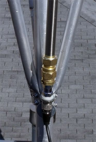
I will build this connection for the next one, but with four stand-offs for a four radials cone:

All bets are off with me Homer until I get a good confirmation from Shockwave or Bill on what they think, regarding what I sent you earlier via email.
This is a problem with Eznec, that I was assured in the beginning was not a problem, having to make sure the wires in Eznec were all constructed in some particular order regarding wire end 1 and end 2, or was just so so order fine.
I know doing so so is not the desired procedure, but I was told that Eznec produced the same results even if you don't follow the recommended procedure in this regard.
If you look at these models you will see that the performance results are the same, the antennas are structurally identical 1/2 wave yagi radiators, and look much alike, but the current distributions and the phase are all different.
This is what I just recently became aware of, and I don't like it, else we need a positive and well noted solution and instruction in the Wires section of the Manual.
Plus if you use the auto feature for making radials using Eznec, it will not fix the problem with current distribution and phase. It just aggravates the problem even more, by the way it connects the wires, and looks to me to possibly produce the worst situation regarding phase.
I've read a lot of Cebic stuff on Eznec, and I don't recall ever seeing anything about this problem there either.
I do hold out hope that it is just me that has the problem however.
I won't be able to look at it in Eznec until I reinstall it. The computer I used crashed and this one is a used replacement. I have to put the program on an older XP unit because it does not support the Windows 7 operating system.
Looking forward to any answers . . .
Looking forward to any answers . . .
I don't know, Booty.
Since i got the 259b I've used it exclusively, and I have no idea whether it would have been any different without it.
I've used it to build three antennas since receiving it: the .64, the EFHW, Sigma 4 redo.
I achieved fair results on the .64 - it acted typical of such an antenna with nothing outstanding I could remark about.
The EFHW is doing better than the A99 1/2 antennas I've used in the past with its last configuration that includes a GP radials. I am unable to say it is because of the 259b . . .
The Sigma 4 works when in the air, but so far I have been unable to get it to read ideally on the 259b. Achieving a low VSWR is easy enough, but the R= and X= are never where you'd want to write home about. To date I have never known of anyone reporting anything on whether their Sigma.Vector antennas look good on an analyzer so I just scratch my head on that one. I'll build one more from scratch and try again in due time.
Homer, I was reading this old thread looking for some information about the Sirio SD-27 antenna, and I noticed the comment above.
Since you've rebuilt your idea for the New Vector 4000, and it is producing much better analyzer results, can you now share with us what the issues were that overcame the issues you were scratching your head about, what made the difference?
Also, did you build one of these vertical SD-27 antennas or something like it in the past using a gamma match or did you direct feed it? If you know, either way, how did it look on your analyzer?
It indicates where the voltage maxima and minima are in the geography of the antenna, if you cant find where the current maxima and minima are located within the geography of the antenna stick 1.5KW up its ass then go around the antenna with your finger and see which part of the antenna kills you**Jump_im**Those bulbs will light up because of voltage. The radiated signal is current, not voltage. So, those lights aren't really an indication of how much signal is being radiated, or where.
- 'Doc

Following your advice to start with the standard dimensions for the Vector 400 I started over again on the rebuild and did that for the over all lengths of the Vertical and the cone radials. Additionally I made sure the loop was exactly what it should be. Bob had questioned the dimensions of my dog bone on the gamma, so I rebuilt it, but stronger than before using 3/4" x 3/16" aluminum bar instead of 1/2" x 1/8" as before. I also used the idea we hasd discussed about some stand off of the radials at the bottom of the cone where they attached to the vertical. Because the EZnec model seemed to work out better with some stand off we considered the possibility that the real antenna might benefit from that. too. Previously my antenna.s radials went straight out from the vertical at the prescribed angle of about 30 degrees, but did not stand off. I made the mount for the bottom of the radials with right at 1-1/4" stand off before the cone tubes began their ascent toward the hoop.Homer, I was reading this old thread looking for some information about the Sirio SD-27 antenna, and I noticed the comment above.
Since you've rebuilt your idea for the New Vector 4000, and it is producing much better analyzer results, can you now share with us what the issues were that overcame the issues you were scratching your head about, what made the difference?
At that point I still seemed to be unable to get a good match on the MFJ-259b, so I decided that for whatever reason my gamma match was not able to match my antenna. I made another gamma match using increased diameters for the gamma tube, and the gamma rod. The length of the tube remained the same as before. The rod I had was about 4" shorter than the original length, but I thought I'd try it before buying another. It worked just fine. Additionally I followed the suggestion you had made about the possibility that the brass fittings at the bottom of the gamma tube may have been read by the RF as a part of the gamma tube length and removed the brass fittings from the bottom using instead an aluminum "el". Whether this actually helped or not I can not say, but I do know it slimmed up the parts at the conjunction of the feedpoint and the cone radials where there may have been some capacitance that was not contributing toward the mismatch of the antenna to 50 Ohms. Regardless, I now had a Gamma tube that was 5/8" x 17", a rod that was 1/2" x 32" with the ability to bring the match right into line.
When I had this done I found the antenna had less apparent bandwidth than the previous version, but I felt it was a healthier antenna over all.
I have built a vertical tubing dipole both ways. I would have to revisit the non-gamma dipole to answer the question. I also would have to rebuild the one with the gamma to find out.Also, did you build one of these vertical SD-27 antennas or something like it in the past using a gamma match or did you direct feed it? If you know, either way, how did it look on your analyzer?
In the next few days I will be sending my analyzer in for recalibration. I dropped it on the concrete floor. It now will not read 50 Ohms on any proven 50 Ohm load. It reads a consistent 63 Ohms instead.
dxChat
- No one is chatting at the moment.
