
You are using an out of date browser. It may not display this or other websites correctly.
You should upgrade or use an alternative browser.
You should upgrade or use an alternative browser.
-
You can now help support WorldwideDX when you shop on Amazon at no additional cost to you! Simply follow this Shop on Amazon link first and a portion of any purchase is sent to WorldwideDX to help with site costs.
-
A Winner has been chosen for the 2026 July 4th Retevis RA89R Giveaway! Click Here to see who won!
CB tool needed
- Thread starter dxing.bruce
- Start date
Homedepot may have it belowis the link i dont know the meassurment of mic socket
https://www.homedepot.com/p/Sunex-2-Prong-Radio-Trim-Nut-Socket-SUN392102/301651035
Trim nut socket. That's it. I could not remember the name of it.
If someone has this socket, could you measure what size it is so I can make some at work. I have a bunch of extra sockets just need some specs.

I bought one of these sockets a few years ago. it was about 20.00 shipped and it only lasted on about 2 radios. the tabs broke off very easy. I made a pair of needle nose pliers to work . got a pair with a small tip on them and bent them so I could get on to the nut with out it hitting the stud.,still have them and they work just great.
the tabs broke off very easy.
Sure sounds like the antenna-mount socket we were getting from NAPA once upon a time. Had the same problem.
73
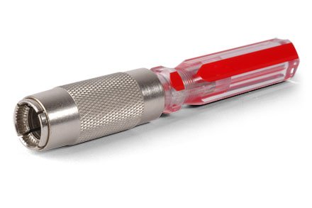
The inside of the socket must be round, with no flats on it. Mine measures dead nuts-on at 5/8 of an inch inside dia.
If the wall of the socket is too thick, it might not reach into a nut that's flush the panel opening. The 1/16-in. wall thickness on this socket makes the overall OD 3/4 inch. The teeth are also 1/16-in wide.
The stainless version with the dimensions above is 4 inches long, with the upper 2 inches knurled to improve grip.
I'm just very pleased they hardened the thing. Much better than the car-antenna trim-nut tool.
73
Keep in mind that most Mic jacks have a flat side, and the body won't turn.And if it was off a radio that used a lot of different mics, it may also be cross-threaded - meaning stripped - I've had those too...
For that - it's more drastic, you unsolder EVERYTHING off the pins of that jack connector - and you unscrew from the back - the internal side, holding the nut in place and pulling from the backside - slowly turn it out - and as said - cross threaded ones are the most difficult.
dxing.bruce,
Just an off the wall thought-Would it be easier to remove the volume pot/power switch?
73's
David
I can't as these radios won't let you take the face off the circuit board that holds the switches unless you get the nut off the 4 pin mic jack.
It's a pain in the ass as it has 4 indents where a tool is needed to get it off, I tried needle nose pliers but the one I have are too thick at the tip to get into the cut outs.
Ok, got some more info for you...
You will now see why PC-122 never made it into the Top-10 Best Radios out there...
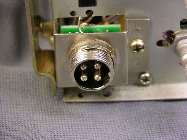
Here's what you got to deal with front the component side that houses the switches.

Now, here's your Mic Jack...and how few choices you have...but you do get an "Out" from this...

Here's another view...

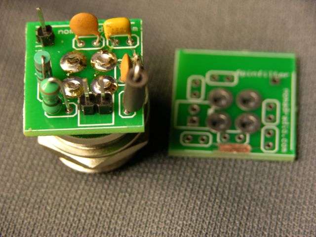
Now, maybe I'm doing this wrong but I'm not intentionally trying to destroy any radio...
The above is what you should have in your radio - not much to hold it on.
So all the shielding, support, and any torque done to the front panel - was borne by the plastic frame case.
Now you know why I'm a big fan of cable - especially flat ribbon ones...
And why I mentioned the unsoldering - it's the easiest way to remove the card.
Yes, as you can see in the 2nd photo - there is a flat spot and yes, they do use Loctite.
Now you should be able to get at the volume control.
But do you have problems with the Mic jack - I don't recommend you try to remove it - just unsolder it...remember that it has a shield ring too...
But, if you have such an issue with the Mic jack and it can't be removed - you have a choice, use the wrench, or make your own or back it out (worst option) - but in any fashion, the nut HOLDS the whole side of that front panel and the phillips screws hold the card to that plastic panel and bezel.
So, what I've done - to get this one off was - unscrew all front panel nuts from volume control and remove all back front panel screws (faceplate stuff) - it does help if you unsolder the ribbon cable from the main PCB to the front panel of the radio and the power wires to the ON-Off control. Allows you room to work.
Unsolder the mic jack 4 pins and you should now be able to remove the entire card, remember this is an assembly for there are foam spacers, washers and spare shims for that front panel - so once you've removed - this will all need to go back in - including the "mask" that may be present for both the channel display and LED meter S/RF.
As far as removal the nut from the front panel - that is all plastic - so no matter what you can try to use the "flat" on the pin side of that surface mating flange to hold the part while you tap out , back out that turn-nut and work against it's glue.
I've used Isopropyl and White Gas on Qtips to just loosen the goo to allow the nut to turn - there is a washer behind it so as you back it out and find it binds- remember that you may lose the flat - but you have a washer to press this back together if needed.
I've had to "jam" a flatblade screwdriver into the nut groove and the plastic housing just to hold it while I've turned out back out that nut.
But here's the thing - these don't usually go bad - just get cross threaded - if you have time - just use another ring nut to clean off those threads...IF it's intact just leave it alone and unsolder it - don't back out any nut if you don't have to on that mic-jack at least that's what everyone in this thread is going with this - I wouldn't...
Just UNSOLDER that 4-pin, power wires to ON/OFF switch and ribbon cable from the main PCB side, remove the screws and pull card. The Volume, Squelch, RF Gain, Clarifier and all switches come off together as a single assembly.
Hope this helps!
:+> Andy <+:
You will now see why PC-122 never made it into the Top-10 Best Radios out there...
Here's what you got to deal with front the component side that houses the switches.
Now, here's your Mic Jack...and how few choices you have...but you do get an "Out" from this...
Here's another view...
Now, maybe I'm doing this wrong but I'm not intentionally trying to destroy any radio...
The above is what you should have in your radio - not much to hold it on.
So all the shielding, support, and any torque done to the front panel - was borne by the plastic frame case.
Now you know why I'm a big fan of cable - especially flat ribbon ones...
And why I mentioned the unsoldering - it's the easiest way to remove the card.
Yes, as you can see in the 2nd photo - there is a flat spot and yes, they do use Loctite.
Now you should be able to get at the volume control.
But do you have problems with the Mic jack - I don't recommend you try to remove it - just unsolder it...remember that it has a shield ring too...
But, if you have such an issue with the Mic jack and it can't be removed - you have a choice, use the wrench, or make your own or back it out (worst option) - but in any fashion, the nut HOLDS the whole side of that front panel and the phillips screws hold the card to that plastic panel and bezel.
So, what I've done - to get this one off was - unscrew all front panel nuts from volume control and remove all back front panel screws (faceplate stuff) - it does help if you unsolder the ribbon cable from the main PCB to the front panel of the radio and the power wires to the ON-Off control. Allows you room to work.
Unsolder the mic jack 4 pins and you should now be able to remove the entire card, remember this is an assembly for there are foam spacers, washers and spare shims for that front panel - so once you've removed - this will all need to go back in - including the "mask" that may be present for both the channel display and LED meter S/RF.
As far as removal the nut from the front panel - that is all plastic - so no matter what you can try to use the "flat" on the pin side of that surface mating flange to hold the part while you tap out , back out that turn-nut and work against it's glue.
I've used Isopropyl and White Gas on Qtips to just loosen the goo to allow the nut to turn - there is a washer behind it so as you back it out and find it binds- remember that you may lose the flat - but you have a washer to press this back together if needed.
I've had to "jam" a flatblade screwdriver into the nut groove and the plastic housing just to hold it while I've turned out back out that nut.
But here's the thing - these don't usually go bad - just get cross threaded - if you have time - just use another ring nut to clean off those threads...IF it's intact just leave it alone and unsolder it - don't back out any nut if you don't have to on that mic-jack at least that's what everyone in this thread is going with this - I wouldn't...
Just UNSOLDER that 4-pin, power wires to ON/OFF switch and ribbon cable from the main PCB side, remove the screws and pull card. The Volume, Squelch, RF Gain, Clarifier and all switches come off together as a single assembly.
Hope this helps!
:+> Andy <+:
Last edited:
I don't think they spend the extra money for LocTite. A drop of QD solvent tends to loosen it okay.
Pretty sure the schmoo they use to lock that round nut is plain old clear enamel.
Like the clear nail polish we use to lock it back down. A drop on the flat of the socket's bushing against the round nut is all it takes. Capillary forces will pull the liquid down into the threads under the nut without fouling the exposed threads you want to keep clear for your mike plug.
Acetone will probably loosen the factory schmoo okay, but I don't keep that solvent on the bench.
73
Last edited:
Acetone will probably loosen the factory schmoo okay, but I don't keep that solvent on the bench. 73
Just be careful. Acetone will wreak havoc on plastic faceplates.
- 399
I'm just trying to figure out why they need to remove the ring - it's far easier to leave the jack mounted on the front panel - at least you have an alignment "pin" setup.
There really is not all that much to this - just the Volume control and Channel Selector are threaded and the mic jack is the only one that has issues with disassembly. So remove the knobs and nuts for Volume and Channel and if you can't remove the lock-ring for the mic, just unsolder it - there are two boards up front
As said earlier - if the jack is that screwed up - most of the time I've seen the panels' cracked too.
Usually from someone kicking it with their knee in some type of accident with the vehicle.
The original PC-122 as well as others from Uniden - directly wired from the 4-pin to the board thru a wire harness.
The XL was designed like a modular - only with ribbon cable - it's not using soldered edge connector. Its only Achilles was the Clarifier control that everyone poofed when they tried to unlock it. The Channel selector was it's own mess with it's edge connector for the LED display - but there was no torque to that side of the front assembly except for dropping it on it's face usually damaged the wafers.
I just attached some pics. Don't complain about dust or lint - you folks can decide what to do with them.
:+> Andy <+:
Attachments


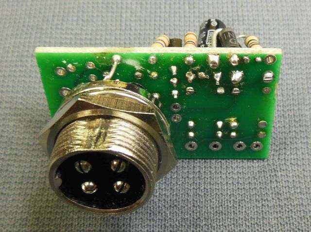
We routinely remove the factory nut to convert radios from 6-pin RCI to 4-pin Cobra/Galaxy.

Got tired of wiring the chokes and caps by hand.
This one goes into the Uniden-made 40-channel SSB CB radios with 5-pin mike sockets.
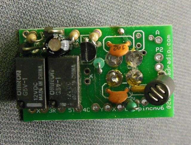
This one has had some teething problems, causing the radio's receiver audio to cut out. Like maybe I used a relay with a current rating that's too small, maybe?
Gotta get to the bottom of that problem. Hate to scrap another batch of
them.
73
Got tired of wiring the chokes and caps by hand.
This one goes into the Uniden-made 40-channel SSB CB radios with 5-pin mike sockets.
This one has had some teething problems, causing the radio's receiver audio to cut out. Like maybe I used a relay with a current rating that's too small, maybe?
Gotta get to the bottom of that problem. Hate to scrap another batch of
them.
73
I believe this tool will do what you want:
you can get them on amazon, or here:
https://www.stewmac.com/Luthier_Tools/Types_of_Tools/Wrenches/Adjustable_Toggle_Switch_Wrench.html
LC
you can get them on amazon, or here:
https://www.stewmac.com/Luthier_Tools/Types_of_Tools/Wrenches/Adjustable_Toggle_Switch_Wrench.html
LC

dxChat
- No one is chatting at the moment.