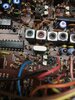
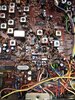
Hi. Could one of you fine folks help me out with the location of r187 on this board. It's in the clarifier circuit apparently, but I can't seem to locate it. Doesn't seem to be any board layouts available anywhere & it's difficult to see and/or find alot of locations on this board. I've looked as closely as I can around some of the other clarifier components, such as d35/d36, but am not seeing r187. I need to check if it there or not or cut, because someone previously screwed up the clarifier job & I'm trying to straighten it out. I had already found & corrected several mistakes, but I can't find that dang resistor location. It might be well hidden. I'm trying to locate it via the schematic but the way the schematic is drawn, it's still hard to find. Eyesight not that good at this point. Using a lighted magnifier but no luck so far.
Really appreciate some help finding r87 location.
Thanks in advance
I hope replies go direct to my email...
Really appreciate some help finding r87 location.
Thanks in advance
I hope replies go direct to my email...