
A digital frequency display for the Tram D201 radios would be nice, but there's a problem. The only displays that fit the VFO dial window are LCD. Black dot-matrix numbers on a green backlighted background.
Customers don't like LCDs. Neither do I.
Tried it. It worked, but I didn't like it.
But every LED frequency display I can find, since the 1980s-era PDC256 is just too big to fit inside a window that's 2 and 1/8 inches wide.
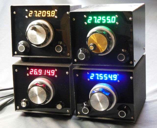
The solution, of course is to roll your own. Never design and build what you can just buy. Especially if it comes from China for less money than you could ever hope to build one yourself. The SanJian Studio model PLJ-6LED frequency display has all the features you need, but one.
IT'S JUST TOO BLOODY BIG!
Solved this problem in the Siltronix VFO by removing the aluminum front panel and substituting one made from smoked plex.
Can't do that with the D201.
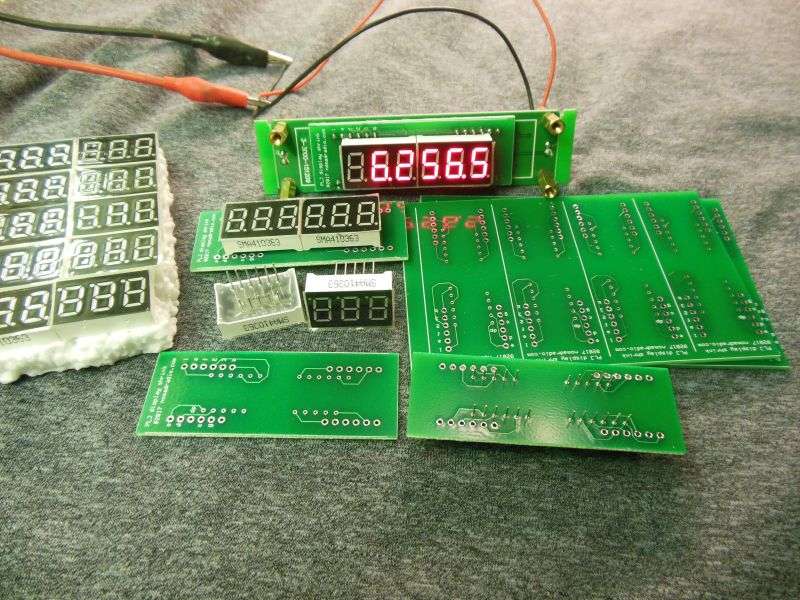
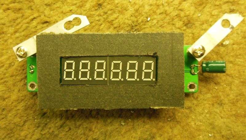
Decided to meet the solution in the middle. The 6-digit counter/display with the too-large digits is just too cheap to resist, and it works just fine. I had pc boards made that accept two 3-digit displays that fit the D201 window and then removed the large digits from the Ebay counter. My board now "piggybacks" on the counter where the original digits mounted.
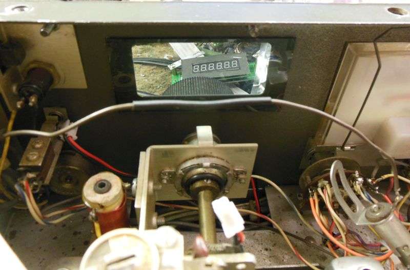
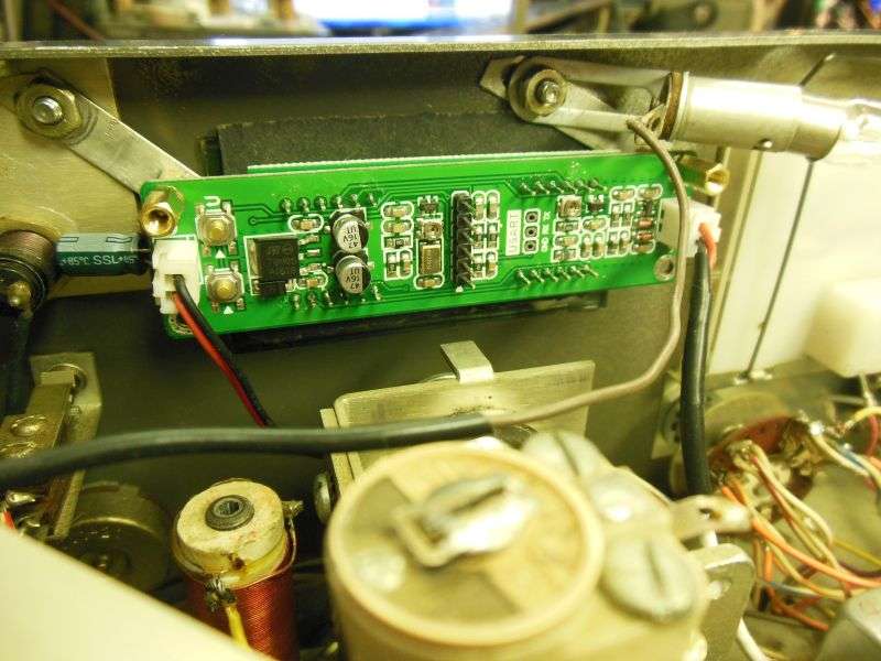
Naturally the VFO tuning capacitor must come out to remove the white plastic dial. Just be sure to get the end-stop screw properly aligned with the capacitor shaft when it goes back in. A new smoked-plex window replaces the original. The right-most dial lamp socket gets removed (on the left in this pic) and the brown wire spliced to power the one behind this side of the meter.
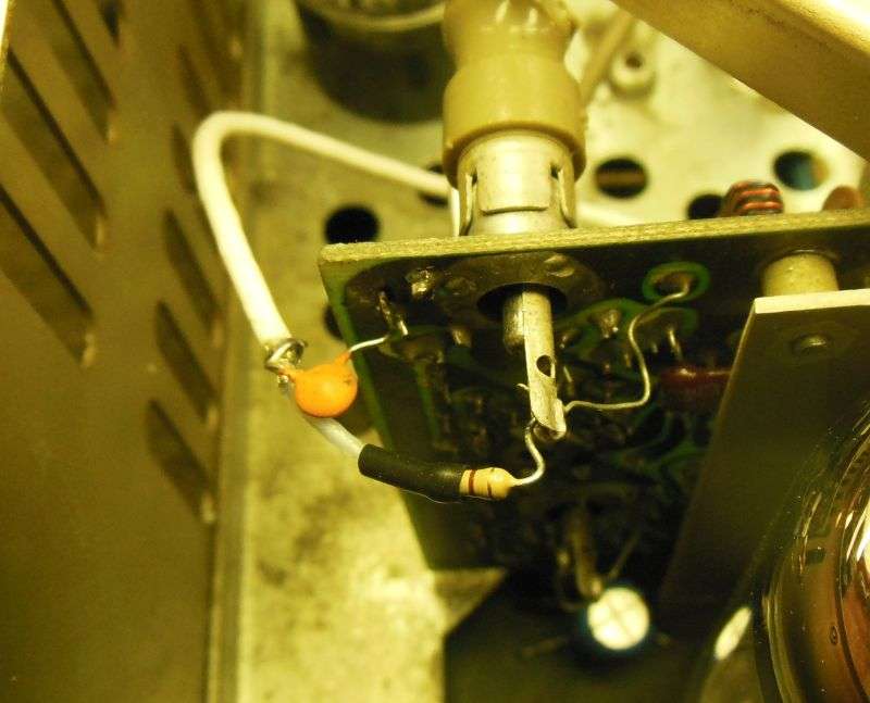
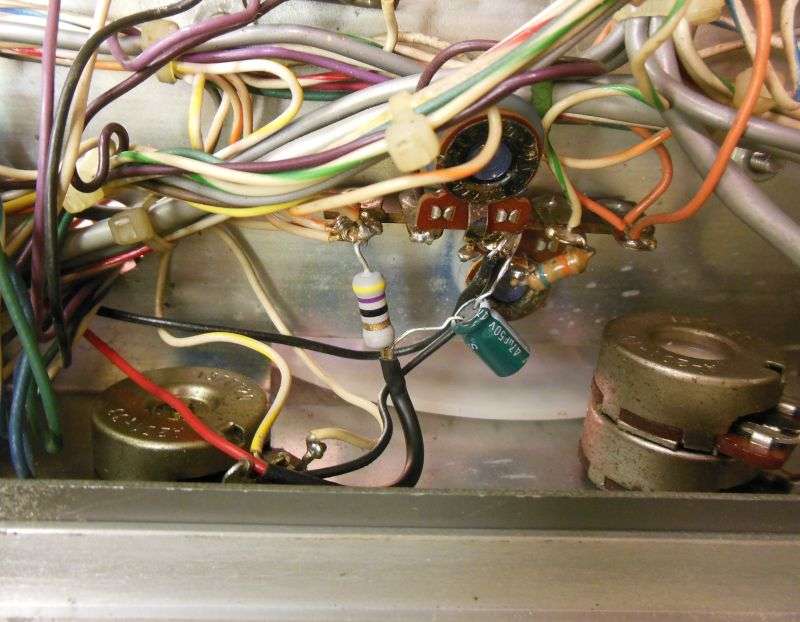
The input cable supplied has two insulated wires, one black and one red. Oddly enough the black wire is the signal input, and the red one is ground. The 40-channel D201A will require a shielded input lead 22 inches long, spliced as close to the display's input plug as possible. The shield does not get grounded to the top socket of the radio's crystal board, but gets grounded for RF only using a .001uf disc cap. The center lead has a 470-ohm 1/4-Watt resistor at the tapoff point, to prevent loading down the crystal board's output signal.
A mask made from black construction paper will block the glare from the radio's meter lamps, and black out the area around the digits.
The power hookup is no big deal, so long as the radio's 14-Volt supply has another 150 mA of capacity, more or less. This radio has our upgraded BA-plus board in it, with a much-larger heat sink on the 14-Volt regulator. A 47-ohm 1-Watt resistor in line with the power tapoff makes life easier for the 5-Volt regulator on the PLJ6 counter board.
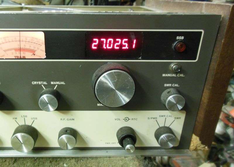
Here's the final installation, ready to use.
Looks pretty legit from the outside, too.
I'm getting close to selling this as a D-I-Y kit. Still need to come up with more-detailed instructions.
Also found that the placement of the two threaded studs inside the front panel above the windows is not exactly the same on every radio. Need to come up with a more-sophisticated mount bracket with slots instead of screw holes.
The question of the radio's 14-Volt power supply overheating is a real possibility. For now I'll just make a package deal of our improved BA board. Has a bigger heat sink on the 14-Volt regulator and won't break a sweat powering 6 LED digits.
Gettin' there.
73
Customers don't like LCDs. Neither do I.
Tried it. It worked, but I didn't like it.
But every LED frequency display I can find, since the 1980s-era PDC256 is just too big to fit inside a window that's 2 and 1/8 inches wide.
The solution, of course is to roll your own. Never design and build what you can just buy. Especially if it comes from China for less money than you could ever hope to build one yourself. The SanJian Studio model PLJ-6LED frequency display has all the features you need, but one.
IT'S JUST TOO BLOODY BIG!
Solved this problem in the Siltronix VFO by removing the aluminum front panel and substituting one made from smoked plex.
Can't do that with the D201.
Decided to meet the solution in the middle. The 6-digit counter/display with the too-large digits is just too cheap to resist, and it works just fine. I had pc boards made that accept two 3-digit displays that fit the D201 window and then removed the large digits from the Ebay counter. My board now "piggybacks" on the counter where the original digits mounted.
Naturally the VFO tuning capacitor must come out to remove the white plastic dial. Just be sure to get the end-stop screw properly aligned with the capacitor shaft when it goes back in. A new smoked-plex window replaces the original. The right-most dial lamp socket gets removed (on the left in this pic) and the brown wire spliced to power the one behind this side of the meter.
The input cable supplied has two insulated wires, one black and one red. Oddly enough the black wire is the signal input, and the red one is ground. The 40-channel D201A will require a shielded input lead 22 inches long, spliced as close to the display's input plug as possible. The shield does not get grounded to the top socket of the radio's crystal board, but gets grounded for RF only using a .001uf disc cap. The center lead has a 470-ohm 1/4-Watt resistor at the tapoff point, to prevent loading down the crystal board's output signal.
A mask made from black construction paper will block the glare from the radio's meter lamps, and black out the area around the digits.
The power hookup is no big deal, so long as the radio's 14-Volt supply has another 150 mA of capacity, more or less. This radio has our upgraded BA-plus board in it, with a much-larger heat sink on the 14-Volt regulator. A 47-ohm 1-Watt resistor in line with the power tapoff makes life easier for the 5-Volt regulator on the PLJ6 counter board.
Here's the final installation, ready to use.
Looks pretty legit from the outside, too.
I'm getting close to selling this as a D-I-Y kit. Still need to come up with more-detailed instructions.
Also found that the placement of the two threaded studs inside the front panel above the windows is not exactly the same on every radio. Need to come up with a more-sophisticated mount bracket with slots instead of screw holes.
The question of the radio's 14-Volt power supply overheating is a real possibility. For now I'll just make a package deal of our improved BA board. Has a bigger heat sink on the 14-Volt regulator and won't break a sweat powering 6 LED digits.
Gettin' there.
73
