
You are using an out of date browser. It may not display this or other websites correctly.
You should upgrade or use an alternative browser.
You should upgrade or use an alternative browser.
-
You can now help support WorldwideDX when you shop on Amazon at no additional cost to you! Simply follow this Shop on Amazon link first and a portion of any purchase is sent to WorldwideDX to help with site costs.
-
A Winner has been chosen for the 2026 July 4th Retevis RA89R Giveaway! Click Here to see who won!
driving a sb220
- Thread starter Number15
- Start date
Not that I recommend it but if you spend enough time and money you can get an SB-220 to do 10K PEP! Everything fits in the stock cabinet other than the new plate supply. That includes the 6 Amperex tubes and the 90 amp filament transformer too. Additional cooling was added all over including small computer fans under the sockets and more than 20 years later, the owner still uses it weekly. There are many reasons not to do a build like this but it only took one to build it. The owner already had 6 matching Amperex 8802 tubes.
If the choice is available you should always select one tube that can match the ratings of the power supply. The more tubes you use the more difficult it is to get them all to match. When they don't match the strongest one is the first to melt down since it hogs the drive power. It's also very difficult to protect many smaller tubes from faults like internal arcs. When the glitch resistor or over current protection is large enough to run several tubes, it also becomes large enough to crush one them them if it arcs. You'll need a unique input circuit to match that 16.6 ohm drive impedance for 6 tubes too.
If the choice is available you should always select one tube that can match the ratings of the power supply. The more tubes you use the more difficult it is to get them all to match. When they don't match the strongest one is the first to melt down since it hogs the drive power. It's also very difficult to protect many smaller tubes from faults like internal arcs. When the glitch resistor or over current protection is large enough to run several tubes, it also becomes large enough to crush one them them if it arcs. You'll need a unique input circuit to match that 16.6 ohm drive impedance for 6 tubes too.

I do not even come close to the amount of electronic knowledge here but i know that limits are made to be broken. Every time someone says something cannot go faster , higher or put out more someone will prove them wrong. People here can say a SB220 will not do that amount of pep watt output because it is electronically impossible have been proven wrong time after time .
4:1 input transformer is 1.32:1 . Would have to handle a full 600W. Bifiller current balun #14ga on 2" #43 @ 10 -12 turns. Balanced output to the Zeds solves a few annoying issues and creates a few easy to solve problems. Careful attention to filament choke reactance ...You'll need a unique input circuit to match that 16.6 ohm drive impedance for 6 tubes
Nope, never dealt with Zeds in multiples of more than two

Y'all better watch them BBI videos and learn something about how many watts those sb220 s can put out.
And that's just with 230 Watts Drive that's what he prefers for everyone to use
Couldn't let this go...
You have a lot to learn.
I'll even point in the right direction.
The Maxwell equations. Learn a little bit more about electricity than Ohms law.
The "Reflections" articles by Maxwell (the other Maxwell)
W8JI , Tom Rauch for some extensive practical applications.
Anything written by Helge O. Granberg for sand state amplifiers.
Almost anything written by William I, Orr (skip the super cathode modulation nonsense) I'll even include a volume of his with this .
It's a start
Attachments
I do not even come close to the amount of electronic knowledge here but i know that limits are made to be broken. Every time someone says something cannot go faster , higher or put out more someone will prove them wrong. People here can say a SB220 will not do that amount of pep watt output because it is electronically impossible have been proven wrong time after time .
I never heard them say it was "electronically impossible" only that it will be exceeding the normal limits of what is sane. The Heath amplifiers have a cheap power supply that is designed to run the amp at what it is speced for. When you try and drive the snot out of it to make 1500-2000 watts out you run the risk of burning up that transformer. The amp may do it but it will not last long. The power supply has a voltage doubler which is a poor way to generate the high voltage and the voltage WILL sag on voice peaks which leads to poor IMD performance. Sure you can upgrade the power supply and redesign the tank circuit but then it's not really a regular SB220 anymore is it? Above all there are two ways to run an amp. The first is the way it was intended to be run and it will run well and be clean. The other way is to try and prove a point about output levels and run the snot out of it and have it spew emissions all over the bands as either harmonics or IMD or just plain splatter caused by flattopping.
Nope, never dealt with Zeds in multiples of more than two
Nor should anyone have too. More than two of them means you have the wrong tubes for the job. This is something a great deal of 11m guys just cannot seem to understand. I would rather BUY an amp with a 3CX3000A7 in it than run an amp with six 3-500Z's even if it was GIVEN to me. Better yet....I would build an amp with a 3CX3000A7 in it.
 That reminds me.....I need to get off my ass and get back to that little project. Got the power supply built now need to work on the RF deck.
 ")
You and me both. I need to get the Frankenstein HA-10 and the NCL-2000 out of the way.now need to work on the RF deck.
Since I parted with two of the three Siltronix VFO drives I had I need to talk to Chris... (makes tuning VacCaps a bit less "hairy")
I'll post the PS parts in the garage thread later.
With boost/buck and taps I can deliver near 3A between 3650 and 4200V now and a bit more if I can swing a deal for ideal iron.
Then there's the linearizing the class"E" deck
Or the old AM "welder" of "rack of crap that absorbs cubic dollars" infamy.
not to mention a variety of 4 to 8 transistor and fet experiments that need modifications for bias and or filter.
Then ...
My iron is from a 1 Kw AM broadcast TX. 3700 volts at 1.2 amps CCS. Good for over 2 amps ICAS. I have a variac in the plate circuit as well as one in the filament circuit. This allows me to vary the plate voltage anywhere between about 2500 and 5000 volts. Got 55 microfarads of filtering. Rectifiers are ED6089 rated at 22 Kv and 30 amps continuous/300 amps surge. They came from a Harris FM broadcast TX. Total weight so far is 218 pounds and that's just the cabinet and power supply.  I am pretty much guaranteed to have the lowest weight to watts ratio of any amp.
I am pretty much guaranteed to have the lowest weight to watts ratio of any amp. We used to measure the value of our designs in watts per cubic inch.(Power Density)My iron is from a 1 Kw AM broadcast TX. 3700 volts at 1.2 amps CCS. Good for over 2 amps ICAS. I have a variac in the plate circuit as well as one in the filament circuit. This allows me to vary the plate voltage anywhere between about 2500 and 5000 volts. Got 55 microfarads of filtering. Rectifiers are ED6089 rated at 22 Kv and 30 amps continuous/300 amps surge. They came from a Harris FM broadcast TX. Total weight so far is 218 pounds and that's just the cabinet and power supply.
It also worked for batteries too. Since these were air borne power supplies we just had to stay under a certain maximum weight.
Now when I design an item I lean towards "Diesel Design" and go for maximum watts per ton.
How is it going on the "Bird Fryer in flight".Nor should anyone have too. More than two of them means you have the wrong tubes for the job. This is something a great deal of 11m guys just cannot seem to understand. I would rather BUY an amp with a 3CX3000A7 in it than run an amp with six 3-500Z's even if it was GIVEN to me. Better yet....I would build an amp with a 3CX3000A7 in it.
I haven't touched it since last winter. It is a labour of love project with an indefinite time limit.
Here is the plate xmfr with the four diode packs rated at 22 THOUSAND volts and 30 AMPS each. Below them are non-PCB oil caps for 55 microfarad of filtering.

Filter caps, main power, filament control and plate control relays. The yellow device on the left is a solidstate time delay relay for the high voltage. Far right is a 30 amp Corcom AC line filter. Just visable in the back is the plate variac. Not seen is the filament variac.

The business end of things with the filament xmfr seen in the upper right not wired at this point. It is now however.

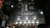
48 inch high Hammond cabinet with full metering. Variac controls are at the bottom.

Close up of meter panel.

Older pic of the vac variables to be used in it. I have a different roller inductor to use. No bandswitch to burn up in this. Vac variables are 1000 uF at 7500 volts (maybe 10KV I forget).

Here is the plate xmfr with the four diode packs rated at 22 THOUSAND volts and 30 AMPS each. Below them are non-PCB oil caps for 55 microfarad of filtering.
Filter caps, main power, filament control and plate control relays. The yellow device on the left is a solidstate time delay relay for the high voltage. Far right is a 30 amp Corcom AC line filter. Just visable in the back is the plate variac. Not seen is the filament variac.
The business end of things with the filament xmfr seen in the upper right not wired at this point. It is now however.
48 inch high Hammond cabinet with full metering. Variac controls are at the bottom.
Close up of meter panel.
Older pic of the vac variables to be used in it. I have a different roller inductor to use. No bandswitch to burn up in this. Vac variables are 1000 uF at 7500 volts (maybe 10KV I forget).
Attachments
dxChat
- No one is chatting at the moment.