Advance Mode:
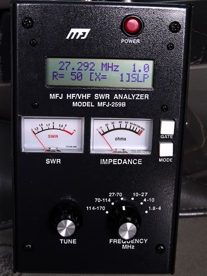
The Resonance Mode primarily draws attention to reactance, displaying reactance on the IMPEDANCE meter.
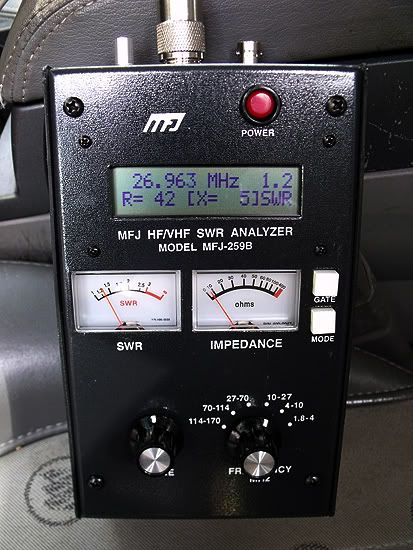
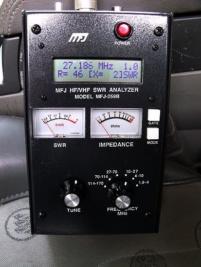
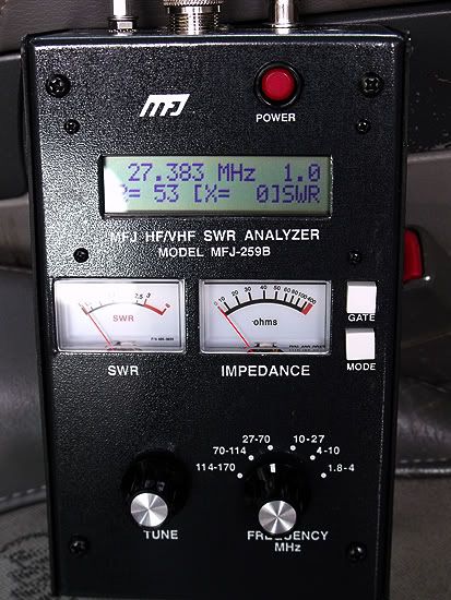
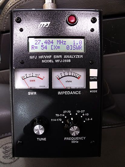
In this mode, the MFJ-259B measures frequency, SWR, resistance (R= ), and reactance (X= ). When reactance is
zero, the system is said to be resonant.
I can measure the antenna in the Main Mode, and the impedance meter will track with the impedance figure, however, in the Advanced Mode, the meter displays reactance in stead of impedance, and they are together in that case.
Main Mode:
The main or opening mode opening menu displays frequency, SWR, resistance, and reactance on the LCD,
along with SWR and IMPEDANCE on the analog meters
OK, I understand now that you were in the advanced mode 5.6 in the manual, Resonance Mode. You were way ahead of me then.
I understand better now, and it's a good lesson to have learn about the operations of the MFJ. I sure wouldn't have learned that from the average guy without a 100 questions trying to get to the bottom of that issue. Most would just get mad before anything valuable was learned. Thanks.
Frankly, I would guess that most users seldom if ever get off into the advanced mode's right away. The idea I come away with from most users is; they generally use the 259B in the Main Mode...as an SWR meter almost exclusively, because understanding the nuances of all the operations and results are not easy.
Now regarding your results. I have a few base antennas that can maintain a good resistive result over a broad range of maybe two megs, which is 5x the width of the CB band, but I don't have one that will show the same reactance, showing X=0 or close as resonance, from channel 1 to 40.
What if you scanned the same antenna in the Main Mode, the power up mode 3.2 I think, like you did in the first Advanced Mode, "Impedance," and posted those results? I would like to see how the impedance meter works at that setting.
Do you have to turn the meter off to get out of the Advanced Modes, or does it just toggle back to the Main Mode after #5 choice?
BTW, I got to thinking about your last statement above and I think the Main Mode 3.3, Impedance meter should show you the complex impedance or Z value, instead of just impedance as we think about it. See here:
View attachment MFJ 259B pp #7.pdf I'm just not sure if the Main Mode is the same as the power up mode or comes up after the mode switch is depressed the first time and then the 1st mode choice then follows with the second depression of the mode switch.
The reason I think you see the numbers tracking so well on your antenna is because the it shows a very good match, with 50 ohms for R and 0 or close for X, with SWR 1.0. If you had any workable mismatch like R=38 ohms X=-9 for example, the digital view would show R=38, but the analog could possibly show close to 50<> ohms in some combinations. I think this is likely to be what happens when you are looking at the complex impedance value of any mismatch which is probably more common. Also read the caution note below the 5.6 about feed line transformation affects when using a feed line for a working line or for tuning.


")


