• You can now help support WorldwideDX when you shop on Amazon at no additional cost to you! Simply follow this Shop on Amazon link first and a portion of any purchase is sent to WorldwideDX to help with site costs.

Need advice on RCI 2995dx repair.

67Malibu

Member
Apr 23, 2010
9
0
11
Hello all. I've pulled a major screw up on my 2995. I was going over the alignment procedure - specifically, I was checking the Driver and Final mA settings and when I went to remove the test lead (aligator clip) from TP7, I accidently shorted TP7 to ground. A small puff of smoke from, or near, Q66 and the radio no longer transmits. All other functions, including receive, seem to be unaffected by the short.

This is the later model 2995dx with board revision EPT695015A. It's an SMT board, so doing major component repair or replacement is beyond my capability.


My question: Can anyone recommend a good shop or Technician who knows their way around inside this radio? Any advice is greatly appreciated.
 

Replace Q66 the 2SB754Y transistor and you have over a 90% chance of restoring normal operation. Your eye must have been in the right place at the time of the short because Q66 is the exact part that will blow up when that test point is shorted to ground. It is the series pass AM modulator transistor that supplies power to the driver and final. It will also stop SSB transmit from working when it burns open as it likely has. This is a simple repair not involving any surface mount parts. If you can wire a mic, you can probably do this. Just make sure you use thermal compound on both sides of the insulator behind the transistor.
 
Last edited:
the 2SB754 is a bit underrated when the radio is "tuned up", and most people upgrade it to a 2SB817.

if you have to replace it anyway, why not upgrade it too!
LC
 
And if the SMT transistor that drives it has also croaked, I have a procedure to replace it with a conventional power transistor bolted to the big heat sink.

Can't remember if I posted it.

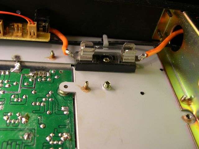
A better strategy is to install a fuse holder and fuse in line with the orange wire feeding DC power to the printed circuit board.

The mobile radio that would be made from this circuit board would draw between 3 and 6 Amps, depending on what decade your radio was made.

You wouldn't hook that mobile radio up to a 30-Amp power supply without a fuse, would you?

But that's what's inside this base-station cabinet. A mobile radio chassis, a 30-Amp power supply, and oh yeah. A linear.

We routinely add a fuse block and fuse in line with that orange wire on any radio of this type that we service. This serves to limit damage when there is a breakdown on that circuit board.

4hAhX1.jpg


73
 

dxChat
Help Users
  • No one is chatting at the moment.