• You can now help support WorldwideDX when you shop on Amazon at no additional cost to you! Simply follow this Shop on Amazon link first and a portion of any purchase is sent to WorldwideDX to help with site costs.

New Sirio Tornado 27

I do believe the roof will have some effect but it should not keep him from getting a good match. In the beginning I said build the thing to spec and put it up. I expected him to pull it down a few times for fine tuning but things got complicated. If he is seeing such drastic changes with jumper length, especially using an analyzer, something is wrong. A bad connection at the antenna, bad coax end, maybe water in the coax.

Even with a metal roof it's odd the a99 had a 1.2 swr...maybe it was the antenna. The only time I've ever saw one with less than perfect swr was when I screwed up installing the pl259 or the antenna had failed internally.

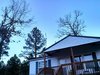
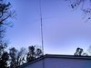
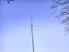
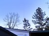
My first base was on a house with a metal roof. The push up pole was fastened to the side of the house and the antenna was about 10 feet above the roof. I ran a bandit 2 (a99 clone) and later an imax with a premade 50 ft piece of rg8 from radio shack. I didn't have an analyzer back then but with the tuning rings in the middle the swr was flat on both antennas. Later on I had a temporary setup with an imax on a fence post sticking up next to a metal chimney and the match was still flat.
 
It's weird no doubt 543. As I said, my old tornado had no issue with tuning. It was pretty well set the tip height and roll with it. Tuned at around 27.385-27.400 area.
Idk why he is having such issues. One can only assume what he/she thinks might be the root cause at this point. With the tip set at 35" it should tune out at about 27.600 area. Adding coax at this point as long as the antennas impedance is at or near 50ohms, the coax length should not matter.
With this said, there is definitely something at play here that we cannot see or can't verify personally. This is why I stated to place a 50ohm dummy load at the end of the coax he is using and see what it reads. Then at least he can rule out the coax as being the issue or not. JMHO. But like I've said before, I am no expert and damn sure don't claim to be!! Just want to help a fella out is all.
 
  • Like
Reactions: Galaxy 959
I don't know for sure the dummy load in place of the antenna would prove the coax was good or bad. The antenna is reactive and the dummy load is not. I'm not an expert either and am just basing this off what I've saw in the past. All I can do is guess but I think he has a bad run of coax or something simple that's being overlooked.
 
  • Like
Reactions: Galaxy 959
Antenna is not set to spec like you stated a couple posts ago. He is currently about 6" short on tip height of where the antenna should be resonant at center of the CB band. He has antenna at 35" at tip And it needs to be at about 41" or so for 27.205. Right now he is tuned for 27.600mhz or so with the measurements he is using (35" tip height). With this said, until he will change the tip length and check with a 1ft coax jumper like he did at tip at 35", how can we truly know if the antenna is tuned correctly. Hope this makes sense.
As far as checking coax being bad. Place dummy load at end of coax and transmit through an swr meter. VSWR should be flat across enitre freq range that can be attained. If VSWR shows bad, then there is an issue with coax. But like I said, until the tip of the antenna is moved to the proper setting and re tested with the same 1ft coax jumper as the last test, we are just guessing at what the issue could actually be. JMHO.
 
I restarted at post 131 because there's alot going on in this thread. My final guess still is that something is wrong with his 50 ft run of coax. Look at how much the swr changed when he added a 3 ft jumper...this is assuming the 3 ft jumper is good. With that much change it seems there is a bad shield connection somewhere and the coax shield is acting as part of the antenna. The only way that roof is causing that much of an issue is if the antenna is laying on it.

I was also thinking that there could be a bad connection between the so239 and radials but since it seems to be spot on with the 1 ft jumper, that he knows is good, I'm sticking with bad coax. I would trust the reading from the 1 ft jumper and the mfj. Hopefully he will get some new coax and it will solve his issue. There's really nothing more I can say without adding more variables and confusion. Coax length shouldn't make this much of a measurable difference unless something in the system is really screwed up.

If he were to put a non reactive load at the antenna end of that bad coax I'll bet he can add and subtract jumpers with little difference in swr. The a99 and bad coax gave him less issues because it is such a broad banded dummy load of an antenna.

The lmr400 is good stuff but if you're trying to keep the cost down look at the place I mentioned earlier. They will install ends for you. Just don't nick the solid center conductor when stripping it if you decide to put the ends on yourself.
 
  • Like
Reactions: Galaxy 959
I'm probably going to get 60' of Times LMR400 from RF Parts with the ends already installed. Its a bit long for my setup but I plan on getting at least a 40' pole to get above these trees. I hope that is my problem. Its tuned fine now but I'm the type of person if something is not right it bugs me to death. I want to figure it out and make it right. I been wanting some better coax anyway. Again I appreciate all you guys help on this.

Is 60' anywhere close to a half wave length. I know I don't have to have that but if its close I would add or subtract a couple feet.
 
Last edited:
The electrical half wave of lmr400 on 11 meters is a little over 15 feet. 60 feet is pretty damn close if it makes you feel better to use 1/2 wave multiples.

If that coax is old and you have any doubts about it it's worth replacing just to eliminate it as a possibility. JMO
 
  • Like
Reactions: Galaxy 959
The electrical half wave of lmr400 on 11 meters is a little over 15 feet. 60 feet is pretty damn close if it makes you feel better to use 1/2 wave multiples.

If that coax is old and you have any doubts about it it's worth replacing just to eliminate it as a possibility. JMO

Its almost 2yrs old is all. I'm about positive the ends are just not correct. I don't think its the cable itself. I just have a 30 watt $3 iron. I just put these Amphenol ends on when I got this new Sirio. When I got it done I hooked it up and radio gave SWR alert and shutdown. I noticed I got the one outside way to hot. So I redone it and it was fine. But still I didn't solder the ground. You cant even see the ground just white in the holes. I couldn't figure out how to strip it where the ground was in the holes to solder. I guess thought the way I done it was fold the ground back and screw the connector on it over the cable cover. Then solder the center pin.
 
Looks good. Looking at the 3rd pic I don't think it's too close to anything.

Folding the shield back works. I know a lot of people that only do it that way and they don't seem to have any trouble, I have made a few jumpers this way (in a rush or being lazy) and they work fine. I prefer to solder them but if you don't have a big enough iron or aren't skilled enough to do a nice solder job you might be better off folding it back. I have found some dielectric grease on the connector and shield helps it screw on easier.
 
  • Like
Reactions: Galaxy 959
I'm running it like it is right now. Works awesome. I'm fixing to order some LMR400 60' with the Amphenol ends already put on. I will see if that changes anything. Like it sets the SWR is 1.2 pretty close across the 11 meter band and the Impedance is just barley over 50. I will report back when I get the coax and get it installed. I'm curious if I will have to adjust my antenna to what it should be instead of having to run it a little short to make it right. I'm getting 60' of coax cause I plan on putting up a 40' pole. Right now its at 26' 8".
 
959, about a month ago I asked you if you could one day give me dimensions for your Tornado27. Can I remind you again in case, after you get your new coax installed, you have to ever take it down to adjust the tip.

959, if you have to take your antenna down in order to adjust your tip length again, could you measure the length from the very bottom at the base of the mount up to the top of the 5 element telescopic whip below section "L"?

The dimensions I want are noted in the Parts List as part #1, the assembled 5 sections telescopic aluminum whip, not including part "L", and part #9, the bottom section assembled with coil, radial hub, connector, and added 1st tubing, as noted between the brackets I made below.

Could you also confirm for me the length of the bottom mounting section below the radial hub?

I'm determined to find out these correct dimensions from some of my buddies, so I can fix my Eznec model.
 

Attachments

  • IMG_0001.pdf
    121.7 KB · Views: 7
Last edited:
Marconi,, just so you know the dimension # 9 your looking for,,,,, the mounting flange/pipe is not a part of the antenna, not connected to the first section, there is the insulated plastic that seperates the 2 parts, the mounting pipe from the radiator
 

dxChat
Help Users
  • No one is chatting at the moment.