
You are using an out of date browser. It may not display this or other websites correctly.
You should upgrade or use an alternative browser.
You should upgrade or use an alternative browser.
-
You can now help support WorldwideDX when you shop on Amazon at no additional cost to you! Simply follow this Shop on Amazon link first and a portion of any purchase is sent to WorldwideDX to help with site costs.
-
A Winner has been chosen for the 2026 July 4th Retevis RA89R Giveaway! Click Here to see who won!
Quick and Dirty Class "AB" mod for KL300p
- Thread starter eagle1911
- Start date
That choke is catalog PN#273-102. Hope that helps ya Liquidh8. ")
(edit) It's a 100 uH (microhenry) choke.
~Cheers~
(edit) It's a 100 uH (microhenry) choke.
~Cheers~
Great stuff here! I decided to do this mod on a little Silver Eagle 200 I got for working on a guys radio last week. It's a 2 X MRF455 class C box with no SSB delay. Since Eagle1911 has the rights to the "Quick and Dirty class AB Mod" I'll call mine the "White 'n' Nerdy class AB Mod"! Attached is a pic.
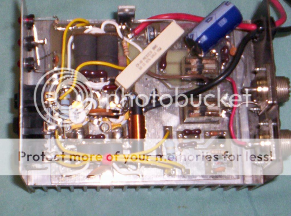
Once i got it all done, it works awesome, looks great on my O'scope, nice clean output. Does about 100W on low output, about 150W on high output, PEP. I did use a different resistor to the TIP42G transistor, as 220 ohms was keeping it "turned on", letting voltage go thru it at all times. I found that 1k ohms works perfect for switching the voltage.
Since this box did not have any SSB delay, I installed a 2200uF 35V capacitor across the relay coil. That gives me a nice delay for SSB, but isn't too long to interfere with AM should I want to use it for that mode.
Great thread, thanks to all that posted info and especially to Eagle1911 for the continued progress of the project!
~Cheers~
That is a smart and cool mod. I have a Comet amp that looks very similar to the amp you have in the picture. I am surprised at the output with the mod, and may have my local tech do the same mod to the Comet. I was thinking that the Comet had built in SSB delay, but I haven't used it in so long I can't remember!
73,
RT307
hi guys i was wondering if there was a way to intergrate the thermal tracking of this bias circuit into the existing bias circuit of a texas star dx500?
Hey guys, a few things. ALWAYS remember.. a bias source needs to be a low impedance, high current, stable source.
The best, cheapest way to do this is with an AUX relay to turn the bias on and off during TX only. Do not forget to use RF bypassing in your circuit, lots of .01 caps and made sure you use RF chokes capable of carrying the current. About 10-22uh works great here.
As far as the wirewound resistor goes and its value, I think it is a bit too low. About 50-68 ohms would probably provide the current needed.
Also, don't forget a lot of these amps have the input transformer grounded directly effectively killing your bias either through a choke, piece of wire with RF beads on it or some other form. It is important to make sure that this is removed at DC potential but NOT at RF. If it is tied to ground, remove the source of the ground connection and use three .01 ceramic disk caps from the two now disconnected points to keep it at ground for RF.
Next..don't forget negative feedback. This is important to control gain (remember biasing an amp increases small signal gain) and you don't want the amp going into self oscillation or producing strange signals from being unstable. A .01 and 100 ohm non inductive metal film resistor at a couple watts works well here for most purposes.
Happy experimenting.
Couldn't you just run the bias feed/regulator rom the relay that is already there - instead of adding one?
Last edited:
Since the existing relay is usually only a double pole and both of those contacts are tied up carrying RF, you're stuck with needing another way to switch this bias. There have been many attempts over the years to skimp on the 3 pole relay by companies like Texas Star. They suffer the consequences of instability and blowing up the chokes used to isolate the RF from the DC.

Thanks for a very useful project and the most excellent photos.
And thanks to all the guys that had some very good observations & suggestions.
I might try this on an amp I have too.
And thanks to all the guys that had some very good observations & suggestions.
I might try this on an amp I have too.
Great stuff here! I decided to do this mod on a little Silver Eagle 200 I got for working on a guys radio last week. It's a 2 X MRF455 class C box with no SSB delay. Since Eagle1911 has the rights to the "Quick and Dirty class AB Mod" I'll call mine the "White 'n' Nerdy class AB Mod"! Attached is a pic.
Once i got it all done, it works awesome, looks great on my O'scope, nice clean output. Does about 100W on low output, about 150W on high output, PEP. I did use a different resistor to the TIP42G transistor, as 220 ohms was keeping it "turned on", letting voltage go thru it at all times. I found that 1k ohms works perfect for switching the voltage.
Since this box did not have any SSB delay, I installed a 2200uF 35V capacitor across the relay coil. That gives me a nice delay for SSB, but isn't too long to interfere with AM should I want to use it for that mode.
Great thread, thanks to all that posted info and especially to Eagle1911 for the continued progress of the project!
~Cheers~
I must admit I like the idea of using a transistor to switch the bias on from the original keying circuit rather than adding another relay. Good job.
PS: The poster before you forgot to RF bypass the diode with a capacitor on his bias mod.
can you eliminate the resistor all together and use a voltage regulator to control the bias?
I started doing some reading on amps and some day hope to make my own amp I was thinking of having a voltage regulator control the biasing of the transistors..
I started doing some reading on amps and some day hope to make my own amp I was thinking of having a voltage regulator control the biasing of the transistors..
Bob; is there a schematic for this mod?the current your bias circuit needs to be able to supply to the transistor bases without sagging below about .6v to keep the amp in class AB depends on the beta of the transistors been biased and the current you draw in the collectors,
m beta sd1446's are pretty high gain devices @27mhz but your 100ohm dropping resistor is too high in value to keep the amp in class AB when you apply higher drive levels
edit you beat me to it
")
I couldn't find it.
I still like the Motorola design I modified. Holds steady. No fluctuation in voltage. Glad to see you on here Bob
No; he didn't. Just thought that you might have a link that shows that mod in schematic form. Appreciate your response.i don't remember if Eagle posted a schematic Robb, look at his other posts maybe he did.
dxChat
- No one is chatting at the moment.
