• You can now help support WorldwideDX when you shop on Amazon at no additional cost to you! Simply follow this Shop on Amazon link first and a portion of any purchase is sent to WorldwideDX to help with site costs.

Robyn 520D low receive / no TX modulation

RichardHartman

Active Member
Feb 7, 2019
80
29
28
50
I have a Robyn 520D that I am working on now. The gentleman stated that he put it up 12 years ago working and when he fired it up recently it didn't work. So when I started here is what I got..

Extremely low receive-AM/LSB/USB but you can hear the hiss increase with the volume. I have to turn the volume all the way up to hear a station that is 2 miles away that normally hits with +10. Also checked with external speaker with same results. There is no reading on the S-meter, meter does work.

Transmit-
AM -1.5w on external meter will not increase or decrease when adjusting vr for AM stays the same. With modulation into the mic it has a slight negative swing. I can talk to station that is about a half mile away and he can hear and understand me.

LSB/USB - no power on key up, extremely low output less than half a watt with modulation. RX is better than AM but still extremely low.

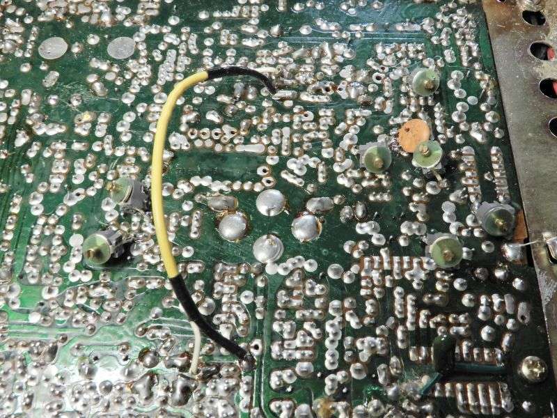
So I started with a recap..

I recapped all the electrolytic caps and c179.
Pulled and checked pre driver/driver/final...all check good.
Rx volume is still the same and Tx modulation still the same. When checking on an external modulation meter I am getting around 20%

I am newer at this and I can go thru the schematic and check each part one by one but if I was more seasoned I would know where to start looking first. What I think if I am correct the audio chip is ok its voltage are consistent with the book and the PA section works and is very loud. The low receive and no Tx modulation I am assuming to be related?
Any help on where to start would be greatly appreciated.

73
Richard
 

If you have not attempted alignment, that would be next. It's possible the adjustments have drifted with age, or got "tweaked" by someone who didn't know what to watch for while twisting them. In particular be on the lookout for any slug-tuned coils that appear to show a peak with the top of the slug DEAD EVEN with the rim of the hole in the top of the can.

If you see this, it's not really a resonant peak. That can has a failed capacitor inside it. The slug position of max inductance occurs with the slug dead even with the rim of the hole. Turning it counterclockwise so it rises above the top of the can will reduce inductance. Likewise turning it clockwise down into the can also decreases its inductance. Since that failed capacitor raises that coil's resonant frequency, maxing out the inductance compensates, but only partway.

Make it appear to "peak" at that position, but it's not really a peak. Just the adjustment's end-of-travel.

Gotta post a video about this someday and just post a link to it.

May or may not have anything to do with your symptom. But it's a common enough fault to at least check for. I'm convinced that long term exposure to high humidity causes this, but don't have proof.

73
I started the alignment made it thru the PLL then the next is the AM receiver
as shown below. I found TP12 underside and the trace is cut and then the can is soldered to the FET. Compared to another Robyn and nothing else on the bottom side seems to be any different. Would anyone know why this would have been done? Stopped the alignment for the moment to see if anyone knows.

73
Richard
20210123_211735 (2).jpg20210123_212449 (3)_LI.jpg
 
Richard,
If you haven't already, consult the information in the link below from Unit399 (a member on this forum).


Look through the page for the modification to the L4 coil for increased receive sensitivity. I performed this on my 138XLR & 139XLR (same chassis) and could tell a big difference.

This doesn't explain your low receive sensitivity but should answer your question about the cut trace.

The can itself should not be soldered to the FET but the full winding of the coil (as opposed to mid-point winding tap) of L4.

I have also installed the 2-FT2 crystal filters in series (as suggested by Unit399) both on my 138XLR and 139XLR and it is indeed a game changer.

73
David
Thank you for the link. That explained it all. And what I thought was the can was the unused leg. Thanks again and I will continue on with the alignment.

73
Richard
 
  • Like
Reactions: Holydvr
If you have not attempted alignment, that would be next. It's possible the adjustments have drifted with age, or got "tweaked" by someone who didn't know what to watch for while twisting them. In particular be on the lookout for any slug-tuned coils that appear to show a peak with the top of the slug DEAD EVEN with the rim of the hole in the top of the can.

If you see this, it's not really a resonant peak. That can has a failed capacitor inside it. The slug position of max inductance occurs with the slug dead even with the rim of the hole. Turning it counterclockwise so it rises above the top of the can will reduce inductance. Likewise turning it clockwise down into the can also decreases its inductance. Since that failed capacitor raises that coil's resonant frequency, maxing out the inductance compensates, but only partway.

Make it appear to "peak" at that position, but it's not really a peak. Just the adjustment's end-of-travel.

Gotta post a video about this someday and just post a link to it.

May or may not have anything to do with your symptom. But it's a common enough fault to at least check for. I'm convinced that long term exposure to high humidity causes this, but don't have proof.

73
Where to start?...
I have completed the RX alignment. This did help increase the volume of the signal but it is still low. This did not change anything with the S meter, still sits at zero. When you inject signal at the antenna with a generator the s meter works?? I was listening to a gentleman right down the road hitting me +30 on my bench radio and nothing on this Robyn's S meter. His audio is extremely loud but the gentleman he was talking to was at 9+ on the bench radio but his audio was alot lower. Is my signal generator signal to strong maybe thats why the S meter works with it???

Next I clean the wax out of the two and contact trace cleaner on the VR's before I get started. I inject 1000hz tone into mic on USB as the book states. At this point I am only showing 1/2 watt output and so I thought it would work itself out as I tune for max. This did not work but as a result of the tune the AM TX at 4 watts , I can achieve 80-100% modulation in AM only. Now at 4 watts it has a negative response to modulation but if I turn it down to 2 wats it will forward swing to 3 watts.

What am I missing??

73
Richard
 
The receiver and transmitter both appear to be 'weak'. The one thing they share that can cause this is the drive level from the radio's frequency synthesizer. This signal is typically called the local oscillator, or "LO". If it's weak, both transmit and receive will be. Choke point for this is the slug-tuned coil L16. If its slug shows the "flush with the rim" position when it's peaked, this is holding back the radio's performance.

73
 
  • Like
Reactions: RichardHartman
The receiver and transmitter both appear to be 'weak'. The one thing they share that can cause this is the drive level from the radio's frequency synthesizer. This signal is typically called the local oscillator, or "LO". If it's weak, both transmit and receive will be. Choke point for this is the slug-tuned coil L16. If its slug shows the "flush with the rim" position when it's peaked, this is holding back the radio's performance.

73
Thank you,

L16 is flush at the rim so with what you are saying I should replace L16 is that correct?

73
 
Thank you,

L16 is flush at the rim so with what you are saying I should replace L16 is that correct?

73
That's one approach. If you have that part on hand. They can be hard to track down for a radio that old.

Our go-to solution is a 30 pf trimmer capacitor. L16 has two pins on one side and three pins on the other.

The trimmer cap's two leads solder to the outer two of the three pins on that side.

The slug gets pre positioned a couple of turns below the rim of the hole, and the trimmer cap is adjusted for max receive signal. Sometimes the slug needs to be farther down inside, sometimes not. A back-and-forth between the slug and the capacitor is sometimes necessary.

This pic shows a near basket-case radio that had seven of these internal caps go bad.

vYRv7m.jpg


The internal cap is almost always connected across the two outer pins of the 3-pin side. Soldering the trimmer to those two solder pads lets it take the place of the failed internal part.

Would be nice if someone worked out the capacitance value of the can's internal capacitor. Service data almost never includes this info.

73
 
Would be nice if someone worked out the capacitance value of the can's internal capacitor. Service data almost never includes this info.
Would this necessarily be a destructive process? Or is there even a known way to read the cap while it's still in the can? I realize since it's in parallel with the coil it may not be as simple as strap a capacitance meter on it or it probably would have been done a long time ago.
 
  • Like
Reactions: RichardHartman
Or is there even a known way to read the cap while it's still in the can?
Ah, yeah. First read the inductance of the coil, and the resonant frequency of a good specimen. Now add a capacitor in parallel with the internal cap and note the new, lower resonant frequency. I won't bore you with the math for now. I'd have to look it up. Just the same, the difference in frequency you get from your added cap should allow calculating the internal cap's value.

More trouble than I've been willing to go to.

73
 
  • Like
Reactions: RichardHartman
Update..

Replaced L16 with one out of a parts board. Exact same result in the position of the slug. Shows max at rim level. Instead of using a trimming cap can I use a fixed value cap say 10pf and then tune the slug again?

Found bad AM-VR and replaced it. I now have an adjustable dead key. I set it at 4w and now it swings up to 6-8w with modulation. Able to achieve 80-100% modulation on external meter. AM TX has been resolved.

So for now here is the current status...

AM - RX is good, TX is good. Still no S meter reading on incoming signal. Meter does work. When I key up the internal RF meter shows 7 when I turn the VR to match the external meter nothing happens, like there is a constant voltage on key up.

SSB - receive is better than before after switching out L16 but still no S meter reading on incoming signal.
TX - Still very little power on SSB like 0.5w and only able to achieve 30-40% modulation which is better than when I first started.

I checked all the voltages on the RX to the meter and voltages all match.

I was hoping that with this updated info maybe it would help narrow down the issue. Thank you for the continued help.

73
 
Last edited:
Ah, yeah. First read the inductance of the coil, and the resonant frequency of a good specimen. Now add a capacitor in parallel with the internal cap and note the new, lower resonant frequency. I won't bore you with the math for now. I'd have to look it up. Just the same, the difference in frequency you get from your added cap should allow calculating the internal cap's value.

More trouble than I've been willing to go to.

73
I did add a 12pF disc capacitor and it moved the slug more to the middle. This did not change anything for RX or TX. Im assuming it was tuned for max already or really close even when it was rimmed. Please let me know if there is any issue with using just a standard disc cap.

73
 
Last edited:

dxChat
Help Users
  • No one is chatting at the moment.