Thank you, I absolutely see everything you stated and you stated it perfectly, the previous owner had obviously turned that resistor down to the output SO-239, was it soldered on, I don't know as when I first removed the board I thought I broke it off the connector, I see the schematic fine now but it's hard with a little phone screen and I did not know the had another section of the relay and it had me confused, thanks !Check your schematic again when you get the chance. That resistor does not connect to the center pin of the output S0-239 connector. (FYI The center pin of the output S0-239 connector attaches to the "Common" terminal of the relay. "Common" meaning it is involved weather the relay is energized-in which case it will connect to the Normally Open terminal-or if it is not energized-where it will connect with the "Normally Closed" terminal)
It appears that R29 (your 10,000 ohm 2 watt resistor) feeds the relative output metering circuit.
One end is attached to the normally open contact of the relay (along with L9 a 30uH choke).
The other end is connected to the junction of R32(a 470 Ohm resistor-yellow/violet/brown), D9(a 1N60 Diode connected to the unbanded end), R31( a 4700 ohm resistor-yellow/violet/red) and C479(a .01 uF ceramic capacitor)
I believe the variable resistor @nomadradio mentioned in an earlier post (VR4/10k) either sets the amount of delay when in the SSB mode or "dials in" the amount of RF power it takes to key the amplifier.
Good luck. Stick with it. You are doing fine.
73
David

You are using an out of date browser. It may not display this or other websites correctly.
You should upgrade or use an alternative browser.
You should upgrade or use an alternative browser.
-
You can now help support WorldwideDX when you shop on Amazon at no additional cost to you! Simply follow this Shop on Amazon link first and a portion of any purchase is sent to WorldwideDX to help with site costs.
-
A Winner has been chosen for the 2026 July 4th Retevis RA89R Giveaway! Click Here to see who won!
Siltronics LA-550 " keying relay issues"
- Thread starter Danzik
- Start date
Thank you and you have no idea how much I appreciate it too !Danzik,
Think of the schematic showing two different systems.
One is the flow of RF. The path your transmitted signal follows when barefoot or on "Standby" and when "Hammer Down" or in the "Operate" mode. Your RF does not flow through the filament circuit of the tubes nor does it flow through the coil of the relay.
The other "system" would include:
- the power transformer. Don't get RF through there but it is necessary for the amplifier to amplify
-the relay(s) coils. No RF flowing there*
-Tube filament voltage flow, fan power (if equipped), meter light bulbs, pilot lights, pre-amp relay controls, switches etc.
* A small bit of RF is "siphoned off" by C43 (a 10 picofarad capacitor) and rectified to a very small DC voltage by D7 and applied to the base of Q1 to provide part of the RF keying circuit.
Don't stress. We are here to help.
73
David
Not only that I am always use to boards that actually have address on them, these boards have nothing so I hold the boards over a light bulb to be able to see where the actual traces even are No it doesn't. Look at the schematic.... Junction of K1/L9/C42/L8....other side to junction of R32/D9 anode. Where are you from?
 and the schematic had me confused as I didnt know this board was broken up into sections as I had my phone zoomed in on that board section that shows the transistors and such, I should have just printed it off
I asked where you were from, because if you were close, I was going to tell you to bring it here. I have one of those amps in near mint condition stored away. Worst case, I would have to find the time and energy to find it and take photos.Not only that I am always use to boards that actually have address on them, these boards have nothing so I hold the boards over a light bulb to be able to see where the actual traces even are

Good deal ! I would have too as there are not many techs around here anymore and I do enjoy working on and learning my own stuff but I always need help from guys like you I could have done even a slight portion of the electronics I have done without assistance from others online because my knowledge of electronic components lack but I am great at soldering , I never take my vintage stereos to anyone, if I can't fix them I can't have themI asked where you were from, because if you were close, I was going to tell you to bring it here. I have one of those amps in near mint condition stored away. Worst case, I would have to find the time and energy to find it and take photos.

Sounds like wiring (wrong, bad or shorted) at the Bypass/Low/High power switch.
The RF sniffer circuit provides a ground to the relay coil. The relay must be getting its positive DC voltage elsewhere. I would start back tracking from the relay coil and find the shorted component.
DO IT SAFELY!!!! REMOVE/LIFT THE CONNECTION FROM THE HIGH VOLTAGE RECTIFIER BOARD TO L7 & L3. KEEP ONE HAND ON THE TOP OF YOUR HEAD OR IN YOUR POCKET OR WHATEVER IT TAKES TO NOT GROUND YOURSELF OUT.
73
David
I am still betting on the transistors.I moved that resistor to where it was supposed to be just to see but no it's still engaging when i turn it off bypass mode
Ya think so ? I replaced both and looked at the schematics tons of times I am still betting on the transistors.
however if you think this I will focus on them ! 

You think they are installed incorrectly or went bad from the shorts we did have and fixed ?I am still betting on the transistors.
I myself am worried more about the PO soldering on the back of it and whatnot, then it apparently blew as I had to repair several tracesYa think so ? I replaced both and looked at the schematics tons of times
Attachments
It seemed to me once i turned the switch to low or high the relay would kick in and just about every wire going into the relay circuit board had power in it I want to check the one coming from the SSB again because it should not have power with the switch in Am position I sure wouldn't think and I could have swore it had around 12vSounds like wiring (wrong, bad or shorted) at the Bypass/Low/High power switch.
The RF sniffer circuit provides a ground to the relay coil. The relay must be getting its positive DC voltage elsewhere. I would start back tracking from the relay coil and find the shorted component.
DO IT SAFELY!!!! REMOVE/LIFT THE CONNECTION FROM THE HIGH VOLTAGE RECTIFIER BOARD TO L7 & L3. KEEP ONE HAND ON THE TOP OF YOUR HEAD OR IN YOUR POCKET OR WHATEVER IT TAKES TO NOT GROUND YOURSELF OUT.
73
David
Makes me wonder if I shouldn't just send you a circuit board we make to do this job. The built-in keying circuits are so bad in some amplifiers that putting in a circuit we trust became our policy. Got tired of hand-twisting lead wires together and it now lives on a printed circuit board.

It has three connections. Four if you want a sideband delay. The metal tab of the switch transistor bolts to a handy chassis screw. This takes care of the ground connection. Mounting it close to the radio jack is best, since a 2-Watt resistor is strung from the center pin of the radio jack to the pad marked "in" on the board. The third connection is a little trickier. It's marked "out", and goes to the cold side of the relay. This would mean removing the two original keying transistors. The 'cold' side of the relay coil is the side that connected to the collector lead of both factory transistors.
Adding sideband delay only requires a switch from the pad marked "SSB" that closes a circuit to ground.
Oh, and the trimmer pot is there to adjust the sideband delay time. Ours is set to around a half second. Not adjustable.
If this sounds good, shoot me your snail mail addy in a PM, or "conversation" as this forum's software calls it. Just consider it the welcome wagon to the forum.
73
Absolutely does sound good and I have Absolutely no problem paying for it ! If anything I owe DX a donation, you guys are great. I will send you my info however I am still going to be working on this thing in the meantime as I really just want to know and find what the problem is with it just for experience and whatnot, thank you !!Makes me wonder if I shouldn't just send you a circuit board we make to do this job. The built-in keying circuits are so bad in some amplifiers that putting in a circuit we trust became our policy. Got tired of hand-twisting lead wires together and it now lives on a printed circuit board.
It has three connections. Four if you want a sideband delay. The metal tab of the switch transistor bolts to a handy chassis screw. This takes care of the ground connection. Mounting it close to the radio jack is best, since a 2-Watt resistor is strung from the center pin of the radio jack to the pad marked "in" on the board. The third connection is a little trickier. It's marked "out", and goes to the cold side of the relay. This would mean removing the two original keying transistors. The 'cold' side of the relay coil is the side that connected to the collector lead of both factory transistors.
Adding sideband delay only requires a switch from the pad marked "SSB" that closes a circuit to ground.
Oh, and the trimmer pot is there to adjust the sideband delay time. Ours is set to around a half second. Not adjustable.
If this sounds good, shoot me your snail mail addy in a PM, or "conversation" as this forum's software calls it. Just consider it the welcome wagon to the forum.
73
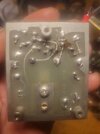
Hi, I don't know if I discovered anything big or not but these components look as if they are installed backwards, schematic show from the base terminal of that transistor a resistor next, then the capacitor but what I actually have is the transistor, a capacitor, then a resistor! Does this matter did someone work on this and put it in backwards?I am still betting on the transistors.


dxChat
- No one is chatting at the moment.