
Got a request for this board, and realized we never got around to showing how it's installed in a Siltronix VFO on our web site. Posting it here is a quick-and-dirty way to procrastinate updating our site.
The Siltronix model 80 and 90 VFOs were built to take the place of one crystal in a 23-channel solid-state CB transceiver.
But using them with a tube-type radio presents a problem. The drive level it delivers is suited to a solid-state oscillator circuit, using transistors powered from 12 Volts or less.
The crystal oscillator circuit in a tube type radio runs at 150 Volts or more. You won't necessarily need ten times the VFO drive level to drive an oscillator tube that you need for an oscillator transistor.
But you need more than the Siltronix design provides.
Usually.
Anyone who swears by using a stock Siltronix VFO is fully free to ignore the rest of this post.
We developed a simple one-transistor circuit that we originally installed inside the Browning Mark 3 SSB transmitter.
Boosts the wimpy drive from the VFO and restores the full power the radio showed when running from a channel crystal.
Before too long my idiot light came on when a customer asked "why don't you just put the thing inside the VFO?"
Why indeed?
So here is a procedure for that. Our web site shows only the transmitter internal install for this board.
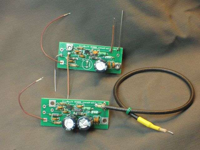
Here is the only pic I found quickly showing the board ready to install. Actually shows both versions. The one with the black coax soldered to it is the one that's installed inside the Mark 3 SSB transmitter.
First thing to check is the age of the VFO. Not a birthday, but a look at the printed circuit board. If you have the later one, the board is mounted in a hole in the chassis deck. The solder side of the board is easily accessible from below the chassis.
** BUT **
If you have an older one, the circuit board is mounted on short pillars, above the solid-metal chassis surface. You can't reach the solder side of the board without dismounting the entire board.
A real pain in the neck.
So for now, I'm showing only the setup for the "later" version VFO.
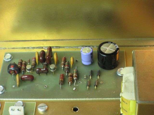
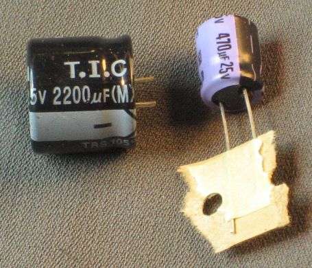
First, the two electrolytic capacitors on the board get replaced. The factory-original parts are too old to trust, so changing them is the only way to prevent wasted time later when the factory parts quit.
They're included with the board. Might not look exactly like these.
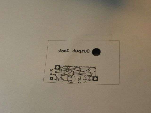
You'll need to drill two 5/32-in. holes in the rear panel. We provide a printed template. The big black dot gets cut out and slides over the RCA socket on the rear.
Weird part is that it's printed in MIRROR IMAGE on the paper.
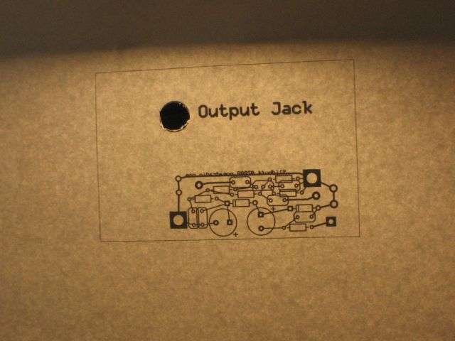
Here's what it the back side of the paper looks like with some light on the printed side.
After carving out the hole for the RCA jack, hold the print side down against the rear panel of the VFO. Mark the two mount-screw holes with a sharpie.
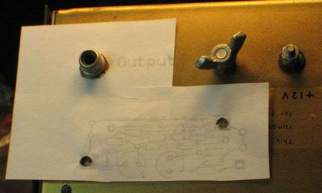
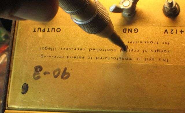
A spring-loaded center punch is worth its weight in copper, just to keep the drill bit from wandering.
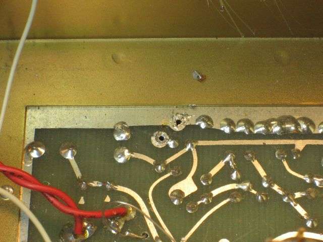
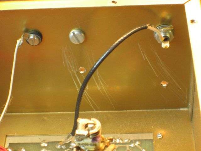
Now would be a good time to remove the skinny black coax from the RCA socket and from the circuit board. Clear the solder from the hole where the coax center conductor was removed. Remove the burrs from the inside of the holes you just drilled. A larger-size drill bit, like 3/8-inch or larger will do the job just fine, or shove the end of a flat file across them. That's where the scratches are from in this pic, pushing the flat end of a file across the holes.
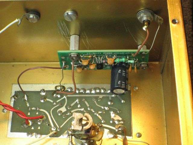
The board gets bolted to the holes you drilled in the rear panel. The power wire in this pic is attached at the far left.
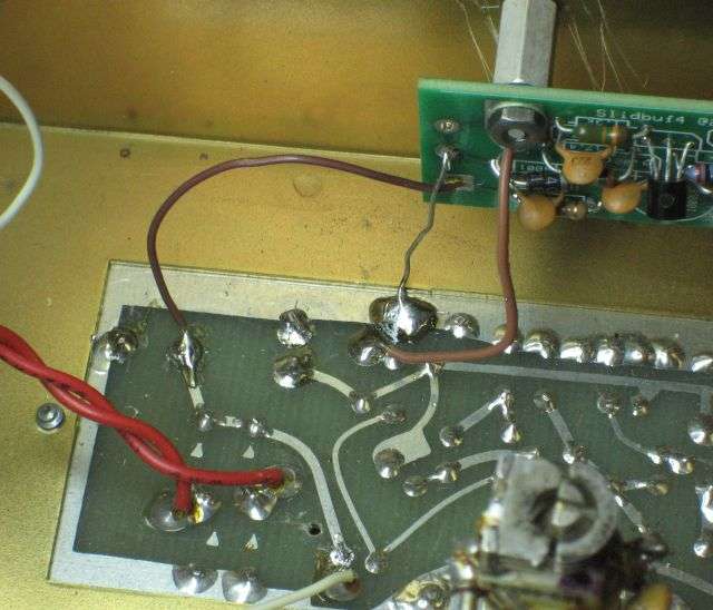
Here's a closer look at the input and power wires. The bare ground wire seen one at each end of the board is no longer supplied. These pics are old, and the first version included two ground wires.
You don't need them.
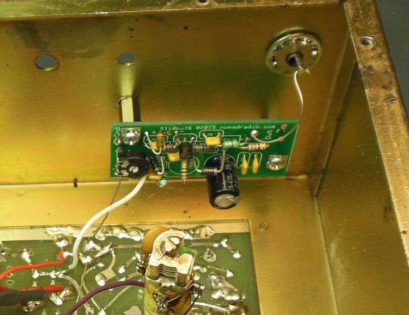
Here's a better pic, showing the level-adjust trimpot. For a tube-type radio, it gets twisted all the way to the right, full blast. That's how we ship them.
But if you decide to use it with a solid-state radio, you can turn down the drive level to prevent the VFO from overdriving the oscillator transistor.
There are plenty of things that can go wrong with a VFO that's over 40 years old. The contact springs against the rear end of the main tuning capacitor's shaft are silver plated. If the tarnish builds up, the tuning can be twitchy and erratic, jumping when you barely touch the big knob in front. The switch behind the left-hand knob on the model 90 will cause the frequency to be erratic when it needs to be cleaned.
We routinely add a ground wire from the ground lug on the big ceramic pillar to the circuit-board foil.
Tightening the mount screw on that pillar is a good idea too, but a good ground on that coil improves stability.
The ground lug bolted directly under it needs a direct wire connection to the circuit-board ground foil.
Hopefully you don't need a picture of that. Couldn't find one.
The price is 45 bucks by PayPal money request or money order in the mail.
Use the PM here if you're interested.
73
The Siltronix model 80 and 90 VFOs were built to take the place of one crystal in a 23-channel solid-state CB transceiver.
But using them with a tube-type radio presents a problem. The drive level it delivers is suited to a solid-state oscillator circuit, using transistors powered from 12 Volts or less.
The crystal oscillator circuit in a tube type radio runs at 150 Volts or more. You won't necessarily need ten times the VFO drive level to drive an oscillator tube that you need for an oscillator transistor.
But you need more than the Siltronix design provides.
Usually.
Anyone who swears by using a stock Siltronix VFO is fully free to ignore the rest of this post.
We developed a simple one-transistor circuit that we originally installed inside the Browning Mark 3 SSB transmitter.
Boosts the wimpy drive from the VFO and restores the full power the radio showed when running from a channel crystal.
Before too long my idiot light came on when a customer asked "why don't you just put the thing inside the VFO?"
Why indeed?
So here is a procedure for that. Our web site shows only the transmitter internal install for this board.
Here is the only pic I found quickly showing the board ready to install. Actually shows both versions. The one with the black coax soldered to it is the one that's installed inside the Mark 3 SSB transmitter.
First thing to check is the age of the VFO. Not a birthday, but a look at the printed circuit board. If you have the later one, the board is mounted in a hole in the chassis deck. The solder side of the board is easily accessible from below the chassis.
** BUT **
If you have an older one, the circuit board is mounted on short pillars, above the solid-metal chassis surface. You can't reach the solder side of the board without dismounting the entire board.
A real pain in the neck.
So for now, I'm showing only the setup for the "later" version VFO.
First, the two electrolytic capacitors on the board get replaced. The factory-original parts are too old to trust, so changing them is the only way to prevent wasted time later when the factory parts quit.
They're included with the board. Might not look exactly like these.
You'll need to drill two 5/32-in. holes in the rear panel. We provide a printed template. The big black dot gets cut out and slides over the RCA socket on the rear.
Weird part is that it's printed in MIRROR IMAGE on the paper.
Here's what it the back side of the paper looks like with some light on the printed side.
After carving out the hole for the RCA jack, hold the print side down against the rear panel of the VFO. Mark the two mount-screw holes with a sharpie.
A spring-loaded center punch is worth its weight in copper, just to keep the drill bit from wandering.
Now would be a good time to remove the skinny black coax from the RCA socket and from the circuit board. Clear the solder from the hole where the coax center conductor was removed. Remove the burrs from the inside of the holes you just drilled. A larger-size drill bit, like 3/8-inch or larger will do the job just fine, or shove the end of a flat file across them. That's where the scratches are from in this pic, pushing the flat end of a file across the holes.
The board gets bolted to the holes you drilled in the rear panel. The power wire in this pic is attached at the far left.
Here's a closer look at the input and power wires. The bare ground wire seen one at each end of the board is no longer supplied. These pics are old, and the first version included two ground wires.
You don't need them.
Here's a better pic, showing the level-adjust trimpot. For a tube-type radio, it gets twisted all the way to the right, full blast. That's how we ship them.
But if you decide to use it with a solid-state radio, you can turn down the drive level to prevent the VFO from overdriving the oscillator transistor.
There are plenty of things that can go wrong with a VFO that's over 40 years old. The contact springs against the rear end of the main tuning capacitor's shaft are silver plated. If the tarnish builds up, the tuning can be twitchy and erratic, jumping when you barely touch the big knob in front. The switch behind the left-hand knob on the model 90 will cause the frequency to be erratic when it needs to be cleaned.
We routinely add a ground wire from the ground lug on the big ceramic pillar to the circuit-board foil.
Tightening the mount screw on that pillar is a good idea too, but a good ground on that coil improves stability.
The ground lug bolted directly under it needs a direct wire connection to the circuit-board ground foil.
Hopefully you don't need a picture of that. Couldn't find one.
The price is 45 bucks by PayPal money request or money order in the mail.
Use the PM here if you're interested.
73

