If you want something that works and looks great then one of Nomads Siltronix VFO's is the way to go they beat the Glenn by a mile

You are using an out of date browser. It may not display this or other websites correctly.
You should upgrade or use an alternative browser.
You should upgrade or use an alternative browser.
-
You can now help support WorldwideDX when you shop on Amazon at no additional cost to you! Simply follow this Shop on Amazon link first and a portion of any purchase is sent to WorldwideDX to help with site costs.
-
A Winner has been chosen for the 2026 July 4th Retevis RA89R Giveaway! Click Here to see who won!
Siltronix VFO, boosting the drive level.
- Thread starter nomadradio
- Start date

Radioman56
Motorola bench-tech
Re: Siltronix VFO., boosting the output drive level (easy fix I just found.?!)
Although I've never had the "joy" of dealing with this particular VFO (the Siltronix model-90) I believe I found an incredibly EASY way to boost its output (some model-years that is) to SIX times its value.!")
Last week, one of my customers dropped-off a pair of Browning Mark-3s, along with a pair of Siltronix 90 VFOs (freq-range #3) for repair of the radios, along with installation / modification for use with the VFO-90s.
Since I've heard there to be some problems with those VFO units not having enough RF output, I decided to first check-out the 2 oscillators before "dealing" with the antique radios...
After first setting them both for correct "ball-park" frequencies, for use with a Mark-3 SSB transmitter, I then checked their peak RF output voltage.
Before even opening them., I measured one unit to have about 50 millivolts of output., whereas the other unit had almost 300 millivolts output.!
Needless to say., they were both disassembled and inspected to discern as to why there was such a GREAT (x6.!) difference in output levels between the two...
At first., I believed it might possibly be, just a weak / aged (hFE gain wise) low output / buffer transistor (Q1).
But after a quick inspection & comparison of the two oscillator boards, I noticed that the bias (voltage-divider) resistor for Q2 (which is R6) was the schematically correct 1k resistor in the unit that was generating the 300 millivolts., while that same resistor in the low output unit (only 50 millivolts) was only 270 ohms.!!
And by the way it was installed, it was positively "OEM stock" installed.!! As to why, I have no idea., except that I know, that some transistor type radio oscillators do NOT want too much input., as then either the receiver or transmitter (depending on what the VFO is being used for) can AND will begin to get "a bit squirrely" in their operation (ie: transmitter output power and / or receiver sensitivity, also depending upon the channel)...
See the attached photo from the original poster of this thread for proof.! There should also be a schematic of the VFO attached (please let me know if the 2 images are not there, as I'm not very "internet-forum savvy)
Starting at the left side of the circuit-board (top-side) it's the 3rd resistor to the right of the 200uh coil (L1), and as can be seen, its color code is red-violet-brown (270 ohm) when it should be brown-black-red (1k ohms).!
Obviously., the with a resistor of only 1/3 the original "stated" value will then actually "pull" more of the RF generated to ground, thus limiting the oscillator's output.!
IMHO., if a user wanted to make the oscillator's output variable (to "suit" multiple radios) one would just keep transistor Q1 at its full output (keeping the 1k Base resistor) and just simply putting a variable carbon-type potentiometer (or trim-pot) at the unit's output.!
Because of the small (in value) 0.001 output capacitor (C8), I believe a high-value of trim-pot would be required as to not "load-down" its high-impedance output., possibly a 100k to 500k trim-pot.??
Anyway., I truly hope the above information I was able to come across (but only because I was lucky enough to have two of the same VFOs., but of two differing manufacturing "runs".!) that I was able to easily diagnose and correct the problem
Regards & 73s,
Eric ( KY8E )
Klein Communications
( facebook.com/radioman55 )
https://www.worldwidedx.com/media/siltronix-vfo-90-photo-of-wrong-r6.6710/
https://www.worldwidedx.com/media/siltronix-vfo-90-schematic-r6-needs-to-be-1k-not-270n.6711/
Although I've never had the "joy" of dealing with this particular VFO (the Siltronix model-90) I believe I found an incredibly EASY way to boost its output (some model-years that is) to SIX times its value.!
Last week, one of my customers dropped-off a pair of Browning Mark-3s, along with a pair of Siltronix 90 VFOs (freq-range #3) for repair of the radios, along with installation / modification for use with the VFO-90s.
Since I've heard there to be some problems with those VFO units not having enough RF output, I decided to first check-out the 2 oscillators before "dealing" with the antique radios...
After first setting them both for correct "ball-park" frequencies, for use with a Mark-3 SSB transmitter, I then checked their peak RF output voltage.
Before even opening them., I measured one unit to have about 50 millivolts of output., whereas the other unit had almost 300 millivolts output.!
Needless to say., they were both disassembled and inspected to discern as to why there was such a GREAT (x6.!) difference in output levels between the two...
At first., I believed it might possibly be, just a weak / aged (hFE gain wise) low output / buffer transistor (Q1).
But after a quick inspection & comparison of the two oscillator boards, I noticed that the bias (voltage-divider) resistor for Q2 (which is R6) was the schematically correct 1k resistor in the unit that was generating the 300 millivolts., while that same resistor in the low output unit (only 50 millivolts) was only 270 ohms.!!
And by the way it was installed, it was positively "OEM stock" installed.!! As to why, I have no idea., except that I know, that some transistor type radio oscillators do NOT want too much input., as then either the receiver or transmitter (depending on what the VFO is being used for) can AND will begin to get "a bit squirrely" in their operation (ie: transmitter output power and / or receiver sensitivity, also depending upon the channel)...
See the attached photo from the original poster of this thread for proof.! There should also be a schematic of the VFO attached (please let me know if the 2 images are not there, as I'm not very "internet-forum savvy)
Starting at the left side of the circuit-board (top-side) it's the 3rd resistor to the right of the 200uh coil (L1), and as can be seen, its color code is red-violet-brown (270 ohm) when it should be brown-black-red (1k ohms).!
Obviously., the with a resistor of only 1/3 the original "stated" value will then actually "pull" more of the RF generated to ground, thus limiting the oscillator's output.!
IMHO., if a user wanted to make the oscillator's output variable (to "suit" multiple radios) one would just keep transistor Q1 at its full output (keeping the 1k Base resistor) and just simply putting a variable carbon-type potentiometer (or trim-pot) at the unit's output.!
Because of the small (in value) 0.001 output capacitor (C8), I believe a high-value of trim-pot would be required as to not "load-down" its high-impedance output., possibly a 100k to 500k trim-pot.??
Anyway., I truly hope the above information I was able to come across (but only because I was lucky enough to have two of the same VFOs., but of two differing manufacturing "runs".!) that I was able to easily diagnose and correct the problem
Regards & 73s,
Eric ( KY8E )
Klein Communications
( facebook.com/radioman55 )
https://www.worldwidedx.com/media/siltronix-vfo-90-photo-of-wrong-r6.6710/
https://www.worldwidedx.com/media/siltronix-vfo-90-schematic-r6-needs-to-be-1k-not-270n.6711/
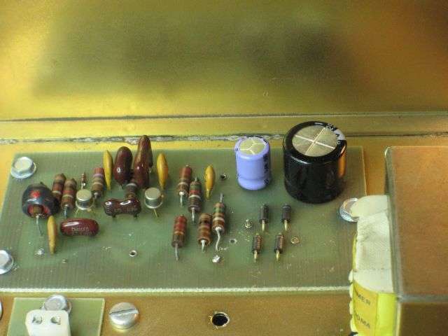
I recognize the two electrolytic caps on that pc board. The ones we used between ten and fifteen years ago when rehabbing a Siltronix. Ran out of the fat 2200uf cap around that long ago. The smaller violet cap is a 470uf. Used up nearly the whole ammo box of those. Also looks as if C3 is different. The factory used a large one, the same physical size as C7 to its right. We change it from the stock 510pf to 390pf. The one we use is typically a smaller physical size than C7.
On the other hand, if we did update this specimen it was more than about 5 years ago. Pretty sure that's when we started removing the zener diode, and using a 78L08 regulator in its place. Definitely more stable.
As for R6, it's the source of base current for Q2, the oscillator stage. A lower resistance value means more base current. Should serve to boost the output, not reduce it.
Umm, okay. R6 is the SINK of base current for Q2, because it's a PNP. Base current for a PNP comes from the negative side of the power supply. Just the same, a higher resistance in series with the base terminal should reduce base current and collector current.
And signal voltage. Gotta pull one of these off the shelf and see for myself.
73
Radioman56
Motorola bench-tech
Umm, okay. R6 is the SINK of base current for Q2, because it's a PNP. Base current for a PNP comes from the negative side of the power supply. Just the same, a higher resistance in series with the base terminal should reduce base current and collector current.
Yes., please check one of yours.!, and if it's not already buffered / amplified with one of those external boards., check-out what a difference R6 can make.!
As the bottom-line is (and just finished that job a few days ago), is that the output did go up from ~50mv to ~300mv, and most likely, not because of any change in base current.
When base current gets too low (or too high), the transistor gets closer to its cut-off point (or its saturation point) both of which are non-linear (along with a large decrease of its amplification)., and it takes sooo little change in base-current to get a transistor to "walk-outside" of its linear-region.
Actually, if one looks closely., both Q2 & Q1 are NPN transistors (of the same part number)., and can be determined by looking at the voltage polarities being applied to the leads of both transistors.
R6 & R7 are simply a voltage divider for the base of Q2., with R2 & R4 being the voltage divider for the base of Q1., both of which are coming from the positive side of the power-supply.! (ie: NPN types).
The increase in RF output was more likely because of the amount of RF voltage being "allowed" to be generated had changed (ie: less "grounding" of Q2's base signal) which is part of the oscillator's "loop"., thus increasing the overall (OEM, non-buffered) oscillator's output...
And thanks for your "input" there Mr. Nomad.!
Regards,
Eric
(the retired "Motorolaian" lead bench-tech of western Mass., now in West "by-God" Virginia
") )
)
Last edited:
Radioman56
Motorola bench-tech
Well my fellow electronics-competent Folks., I just found another inexpensive & easy way to get even a bit more output from your Siltronix VFO 90., or any other brand of VFO (ie: a PAL, Glen, etc.) along with a better (higher) impedance-match, especially for tube-type equipment.!
It's simply using a miniature 4:1 BalUn along with some good quality RF coax cable.!
First-off., I'm reasonably sure that most Folks do use some type of thin RF coax to go from the VFO's output to the radio's Oscillator input., and NOT just some piece of pre-made stereo / audio jumper wire that has a pre-installed "RCA" connector on its end., as using such an "audio-cable" can have drastic attenuation at RF frequencies.!
A good example of such cable can be found here on Amazon:
amazon.com/gp/product/B07L67VJDX
It's a nice quality of RG-316 cable (has a very fine stranded inner conductor & outer shield) in which both the inner & outer insulation is made of Teflon (it's even quite easy to strip-back with common "Miller" type strippers.!) and because of the Teflon, it's virtually impossible to melt while both "tinning" its strands, and soldering connections to it.!
The other "ingredient" is using some type of miniature 4:1 BaUn to help multiply whatever voltage is coming out of your VCO, and to help increase the impedance-matching of the radio's Oscillator circuit (the 75 ohm winding on the VCO output side, and the 300 ohm winding on the radio Oscillator input side)
A good example of such a BalUn can be found here on Amazon:
amazon.com/gp/product/B077PB3DNX
It's nothing more than a standard 75 ohm to 300 ohm "Outdoor TV Antenna Matching Transformer".!
Though this particular one has a large-diameter, mostly hollow, outer plastic housing, as compared to the more typical, small-diameter, mostly solid (white plastic) housing.
The larger housing unit can be easily cracked-open (down its seams) and then able to carefully de-solder & extract the inner Toroidal-wound, BalUn type transformer.!
In this way., one can quadruple the output from their external VFO (ie: 4:1) or in some cases, even more., as a result of possible less "loading" and mis-matching of the VFO's output in the first place.!
I unfortunately still don't know how to attached photos to show-up directly into these posts I make here., and would GREATLY appreciate if someone here would walk-me-through the prosses of doing so.!!!
But., here (below) is a link to a photo I placed in my "gallery" that shows such a set-up I just finished installing into a Browning Mark-III transmitter, in which I now actually get an approximate 20% greater transmitter output carrier using the VFO's output, as compared to when I switch back to any of the "stock" internal crystals of that transmitter.!!
The photo also shows the particular TV transformer BalUn (from Amazon) I disassembled, so as to extract the miniature 4:1 (75 to 300 ohm) transformer.
https://www.worldwidedx.com/media/vfo-balun-transformer-browning-mark-iii.6736
BTW., the "goop" you see holding-down both the coax-cable and the toroidal-wound transformer is NOT "hot-glue". As although it takes MUCH longer to "set" than hot-glue, I've always used "GE Silicone" type of RTV (room temperature vulcanizer) as my glue-of-choice.!
This is because it not only adheres VERY strongly to virtually anything (including glass.!) it's also a bit easier to remove than hot-glue (when / if desired) and will not break-loose (without warning) as sometimes hot-glue will. Also because it has a MUCH longer "pot-time" to "set" (about 30 minutes) than hot-glue does (only 5-10 seconds.!) it gives one the time to "set" an item where one wants, along with being able to "tool" (ie: smooth-out) any excess, or to "form" it into the desired shape
The only down-sides of it are., that it requires at least a few hours to cure enough to "handle" (and 12+ hours to cure-though / become solid)., and your hands / fingers get REAL slippery until you get a chance to do your best at washing the darn stuff off.!
Hopefully this added information and web-links (to my other posts in this Thread) will be of help to others here...
And again, if someone here can direct / help-out this "Forum-inept" (but electronically-competent) guy as to the (I'm sure, simple.?) way to have photos appear in my posts, rather that just "links" to my "gallery" would be just GREAT.!
Regards,
Eric
(aka: TheElectronicsGuy)
Klein Communications since 1980
facebook.com/radioman55
Career Resume
facebook.com/radioman55/posts/543516289675969
Last edited:
Q2 & Q1 are NPN transistors
(face palm!)
Just because they're drawn upside-down doesn't make them the opposite polarity. Sure enough 2N706 is NPN. Always was.
73
Radioman56
Motorola bench-tech
Got a request for this board, and realized we never got around to showing how it's installed in a Siltronix VFO on our web site. Posting it here is a quick-and-dirty way to procrastinate updating our site.
The Siltronix model 80 and 90 VFOs were built to take the place of one crystal in a 23-channel solid-state CB transceiver.
But using them with a tube-type radio presents a problem. The drive level it delivers is suited to a solid-state oscillator circuit, using transistors powered from 12 Volts or less.
The crystal oscillator circuit in a tube type radio runs at 150 Volts or more. You won't necessarily need ten times the VFO drive level to drive an oscillator tube that you need for an oscillator transistor.
But you need more than the Siltronix design provides.
Usually.
Anyone who swears by using a stock Siltronix VFO is fully free to ignore the rest of this post.
We developed a simple one-transistor circuit that we originally installed inside the Browning Mark 3 SSB transmitter.
Boosts the wimpy drive from the VFO and restores the full power the radio showed when running from a channel crystal.
Before too long my idiot light came on when a customer asked "why don't you just put the thing inside the VFO?"
Why indeed?
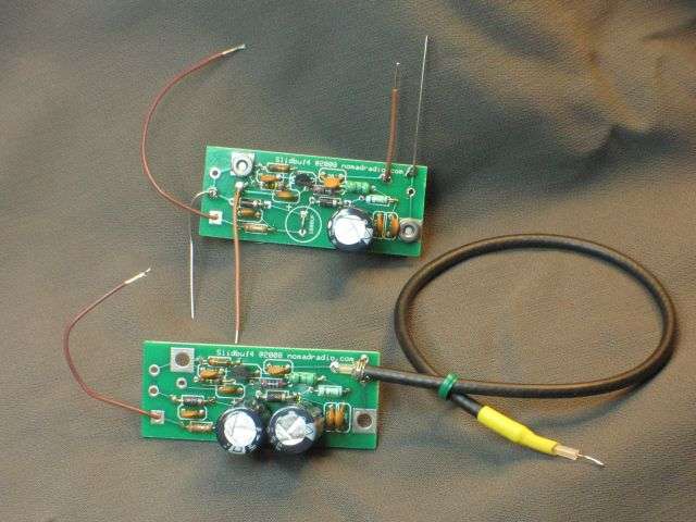
So here is a procedure for that. Our web site shows only the transmitter internal install for this board.
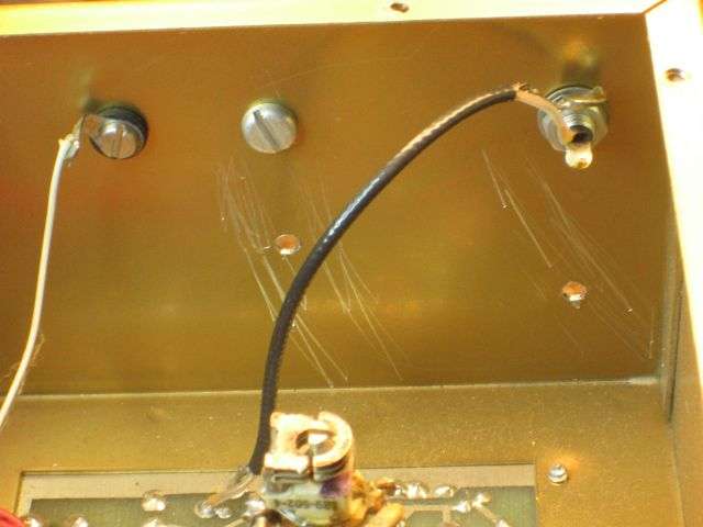
Here is the only pic I found quickly showing the board ready to install. Actually shows both versions. The one with the black coax soldered to it is the one that's installed inside the Mark 3 SSB transmitter.
First thing to check is the age of the VFO. Not a birthday, but a look at the printed circuit board. If you have the later one, the board is mounted in a hole in the chassis deck. The solder side of the board is easily accessible from below the chassis.
** BUT **
If you have an older one, the circuit board is mounted on short pillars, above the solid-metal chassis surface. You can't reach the solder side of the board without dismounting the entire board.
A real pain in the neck.
So for now, I'm showing only the setup for the "later" version VFO.
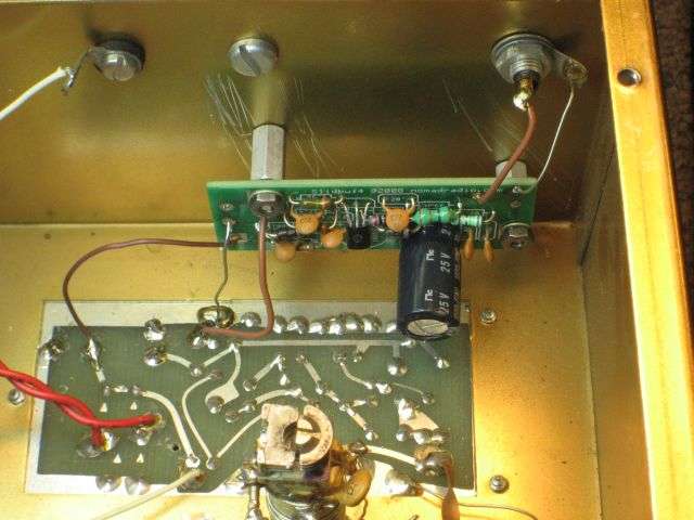
First, the two electrolytic capacitors on the board get replaced. The factory-original parts are too old to trust, so changing them is the only way to prevent wasted time later when the factory parts quit.
They're included with the board. Might not look exactly like these.
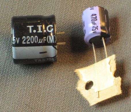
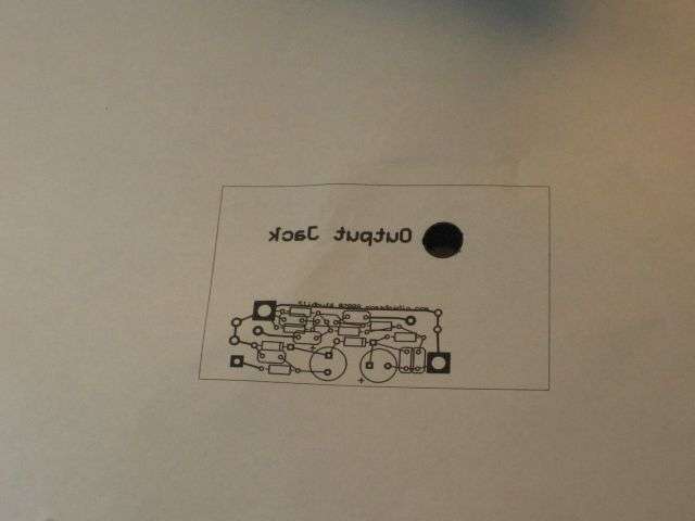
You'll need to drill two 5/32-in. holes in the rear panel. We provide a printed template. The big black dot gets cut out and slides over the RCA socket on the rear.
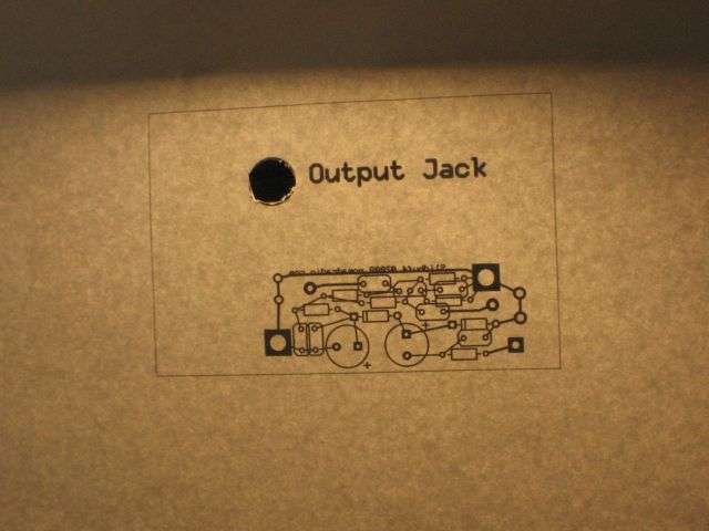
Weird part is that it's printed in MIRROR IMAGE on the paper.
Here's what it the back side of the paper looks like with some light on the printed side.
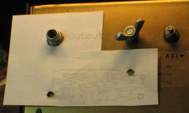
After carving out the hole for the RCA jack, hold the print side down against the rear panel of the VFO. Mark the two mount-screw holes with a sharpie.
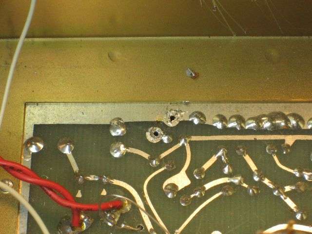
A spring-loaded center punch is worth its weight in copper, just to keep the drill bit from wandering.
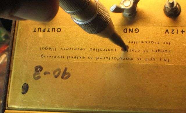
Now would be a good time to remove the skinny black coax from the RCA socket and from the circuit board. Clear the solder from the hole where the coax center conductor was removed. Remove the burrs from the inside of the holes you just drilled. A larger-size drill bit, like 3/8-inch or larger will do the job just fine, or shove the end of a flat file across them. That's where the scratches are from in this pic, pushing the flat end of a file across the holes.
The board gets bolted to the holes you drilled in the rear panel. The power wire in this pic is attached at the far left.
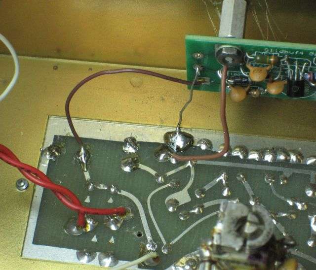
Here's a closer look at the input and power wires. The bare ground wire seen one at each end of the board is no longer supplied. These pics are old, and the first version included two ground wires.
You don't need them.
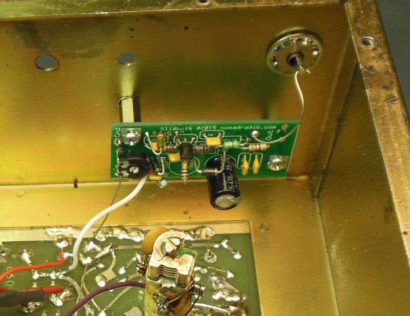
Here's a better pic, showing the level-adjust trimpot. For a tube-type radio, it gets twisted all the way to the right, full blast. That's how we ship them.
But if you decide to use it with a solid-state radio, you can turn down the drive level to prevent the VFO from overdriving the oscillator transistor.
There are plenty of things that can go wrong with a VFO that's over 40 years old. The contact springs against the rear end of the main tuning capacitor's shaft are silver plated. If the tarnish builds up, the tuning can be twitchy and erratic, jumping when you barely touch the big knob in front. The switch behind the left-hand knob on the model 90 will cause the frequency to be erratic when it needs to be cleaned.
We routinely add a ground wire from the ground lug on the big ceramic pillar to the circuit-board foil.
Tightening the mount screw on that pillar is a good idea too, but a good ground on that coil improves stability.
The ground lug bolted directly under it needs a direct wire connection to the circuit-board ground foil.
Hopefully you don't need a picture of that. Couldn't find one.
The price is 45 bucks by PayPal money request or money order in the mail.
Use the PM here if you're interested.
73
Do you have these available?? ThanksGot a request for this board, and realized we never got around to showing how it's installed in a Siltronix VFO on our web site. Posting it here is a quick-and-dirty way to procrastinate updating our site.
The Siltronix model 80 and 90 VFOs were built to take the place of one crystal in a 23-channel solid-state CB transceiver.
But using them with a tube-type radio presents a problem. The drive level it delivers is suited to a solid-state oscillator circuit, using transistors powered from 12 Volts or less.
The crystal oscillator circuit in a tube type radio runs at 150 Volts or more. You won't necessarily need ten times the VFO drive level to drive an oscillator tube that you need for an oscillator transistor.
But you need more than the Siltronix design provides.
Usually.
Anyone who swears by using a stock Siltronix VFO is fully free to ignore the rest of this post.
We developed a simple one-transistor circuit that we originally installed inside the Browning Mark 3 SSB transmitter.
Boosts the wimpy drive from the VFO and restores the full power the radio showed when running from a channel crystal.
Before too long my idiot light came on when a customer asked "why don't you just put the thing inside the VFO?"
Why indeed?
So here is a procedure for that. Our web site shows only the transmitter internal install for this board.
Here is the only pic I found quickly showing the board ready to install. Actually shows both versions. The one with the black coax soldered to it is the one that's installed inside the Mark 3 SSB transmitter.
First thing to check is the age of the VFO. Not a birthday, but a look at the printed circuit board. If you have the later one, the board is mounted in a hole in the chassis deck. The solder side of the board is easily accessible from below the chassis.
** BUT **
If you have an older one, the circuit board is mounted on short pillars, above the solid-metal chassis surface. You can't reach the solder side of the board without dismounting the entire board.
A real pain in the neck.
So for now, I'm showing only the setup for the "later" version VFO.
First, the two electrolytic capacitors on the board get replaced. The factory-original parts are too old to trust, so changing them is the only way to prevent wasted time later when the factory parts quit.
They're included with the board. Might not look exactly like these.
You'll need to drill two 5/32-in. holes in the rear panel. We provide a printed template. The big black dot gets cut out and slides over the RCA socket on the rear.
Weird part is that it's printed in MIRROR IMAGE on the paper.
Here's what it the back side of the paper looks like with some light on the printed side.
After carving out the hole for the RCA jack, hold the print side down against the rear panel of the VFO. Mark the two mount-screw holes with a sharpie.
A spring-loaded center punch is worth its weight in copper, just to keep the drill bit from wandering.
Now would be a good time to remove the skinny black coax from the RCA socket and from the circuit board. Clear the solder from the hole where the coax center conductor was removed. Remove the burrs from the inside of the holes you just drilled. A larger-size drill bit, like 3/8-inch or larger will do the job just fine, or shove the end of a flat file across them. That's where the scratches are from in this pic, pushing the flat end of a file across the holes.
The board gets bolted to the holes you drilled in the rear panel. The power wire in this pic is attached at the far left.
Here's a closer look at the input and power wires. The bare ground wire seen one at each end of the board is no longer supplied. These pics are old, and the first version included two ground wires.
You don't need them.
Here's a better pic, showing the level-adjust trimpot. For a tube-type radio, it gets twisted all the way to the right, full blast. That's how we ship them.
But if you decide to use it with a solid-state radio, you can turn down the drive level to prevent the VFO from overdriving the oscillator transistor.
There are plenty of things that can go wrong with a VFO that's over 40 years old. The contact springs against the rear end of the main tuning capacitor's shaft are silver plated. If the tarnish builds up, the tuning can be twitchy and erratic, jumping when you barely touch the big knob in front. The switch behind the left-hand knob on the model 90 will cause the frequency to be erratic when it needs to be cleaned.
We routinely add a ground wire from the ground lug on the big ceramic pillar to the circuit-board foil.
Tightening the mount screw on that pillar is a good idea too, but a good ground on that coil improves stability.
The ground lug bolted directly under it needs a direct wire connection to the circuit-board ground foil.
Hopefully you don't need a picture of that. Couldn't find one.
The price is 45 bucks by PayPal money request or money order in the mail.
Use the PM here if you're interested.
73
Nomads board works awesome. Highly recommended. And these work great too if he doesn't have anymore.Do you have these available?? Thanks

DDS VFO Amplifier
Does your AD9850 based DDS have inadequate output to drive a vintage transmitter? The solution is here. Barely larger than a postage stamp, our amplifier will terminate your AD9850 based DDS in the proper 200 ohm load and provide approximately 10x voltage gain below 14 Mhz. Convenient large...
casarain.com
Yeah, but the price is 45 bucks shipped.Do you have these available??
The 8-buck surface-mount board shown above makes that look kinda silly. Makes it look like I need to go surface mount with our stuff.
Just the same, ours comes in two versions. One to mount inside a Browning mark 3 transmitter. That way a stock VFO drives it just fine.
The setup to mount inside a Siltronix VFO is a bit different, just need to know which one to ship.
Thanks for asking and 73
So far only the one that mounts inside the Browning Mark 3 SSB transmitter is listed on fleabay: https://www.ebay.com/itm/1168848141...pid=5336136228&customid=&toolid=10001&mkevt=1
The version that fits inside the Siltronix 80 or 90 VFO is set up a bit differently. We'll have them configured and packaged to list on fleabay soon.
Soon. We always say that.
73
The version that fits inside the Siltronix 80 or 90 VFO is set up a bit differently. We'll have them configured and packaged to list on fleabay soon.
Soon. We always say that.
73
dxChat
- No one is chatting at the moment.