• You can now help support WorldwideDX when you shop on Amazon at no additional cost to you! Simply follow this Shop on Amazon link first and a portion of any purchase is sent to WorldwideDX to help with site costs.

TRC-457

lonestarbandit

Supporting Member - WDX 429
Dec 30, 2006
1,063
1,328
173
Ok @unit_399 I completed the mod you advised.
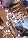
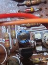
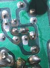
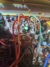
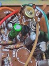
(Eagle eyed viewers may note the diode is standing way up in the air - took the picture before I substantially lowered its position) on the plus side makes it easy to see the changes. Resistor to diode and old blue cap to green cap.

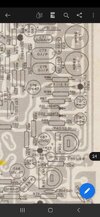
Locate D23 (next to VR7). In the Realistic rigs a 220 ohm resistor is in the D23 location. Replace this resistor with a 1N914 or 1N4148 diode. (observe polarity). This change will make the Realistic 858 mod limiter the same as all of the other brands. Really opens up the audio. Replace C87 with a 10uF 16v electrolytic cap.

My question is what did I actually do by changing the circuit as you said, to match the Uniden circuit? Replaced the resistor with a NTE diode and the cap with a nichicon audio grade cap.
I am told I have great audio but then I did prior to the mod as well. Either way thank you for the knowledge and advice.
 

Attachments

  • 20231103_175331.jpg
    20231103_175331.jpg
    916.9 KB · Views: 21
  • 20231103_175409.jpg
    20231103_175409.jpg
    1.1 MB · Views: 18
  • 20231103_182712.jpg
    20231103_182712.jpg
    1 MB · Views: 18
  • Screenshot_20231103_152312_Acrobat for Samsung.jpg
    Screenshot_20231103_152312_Acrobat for Samsung.jpg
    1.1 MB · Views: 18
  • Screenshot_20231103_152408_Acrobat for Samsung.jpg
    Screenshot_20231103_152408_Acrobat for Samsung.jpg
    1.2 MB · Views: 18
  • 20231103_185101.jpg
    20231103_185101.jpg
    1.4 MB · Views: 19
  • 20231103_190322.jpg
    20231103_190322.jpg
    1.6 MB · Views: 23
  • 20231103_185140.jpg
    20231103_185140.jpg
    1.2 MB · Views: 21
Last edited:

That green cap says BP on it.
It is bi-polar and has no + or -
That was the upgrade I put in per JJs instructions. Nichicon audio grade.20231104_174620.jpg20231104_174629.jpgWhy, is that somehow wrong? Dammit did buy the wrong thing late at night again.....Radio hasn't exploded and audio circuit seems to be working a treat. Saved the original blue one.
 
Last edited:
That was the upgrade I put in per JJs instructions. Nichicon audio grade.View attachment 66133View attachment 66134Why, is that somehow wrong? Radio hasn't exploded and audio circuit seems to be working a treat. Saved the original blue one.
Only thing that's in any danger of exploding is C179 if it's still the original tantalum. It's over by the relay if you haven't stumbled across it yet. Nothing to do with the mod you've done here, but I've had one explode on me. You mentioning the radio hasn't exploded (yet) reminded me of it.
 
Those TRC-457's and 458's and other radios with the same board were (and are) famous for exploding C179. I had a couple go and after that got in the habit of ALWAYS replacing that cap immediately after getting the radio.
 
Those TRC-457's and 458's and other radios with the same board were (and are) famous for exploding C179. I had a couple go and after that got in the habit of ALWAYS replacing that cap immediately after getting the radio.
Hell, now I'll have to open it up again and look. I didn't see any obvious swelling or misshapen caps while I was in there but I wasn't looking for C179 specifically. Thanks for the warning.
 
Hell, now I'll have to open it up again and look. I didn't see any obvious swelling or misshapen caps while I was in there but I wasn't looking for C179 specifically. Thanks for the warning.
It's a tantalum cap, so you won't see any problems until after it goes boom. It's a little blue teardrop with two legs, usually. Replace with the same value electrolytic and you'll be good for about 30 years. I think it's 2.2 mFd at 25 Volts but you should probably check your schematic, I've slept since replacing the last one.
 
Schematics just in case some have same or similar model and might benefit. Picture of radio is pre - mod should be exactly as you find a stock TRC 457 for reference.
 

Attachments

  • Screenshot_20231104_184501_Acrobat for Samsung.jpg
    Screenshot_20231104_184501_Acrobat for Samsung.jpg
    666.9 KB · Views: 18
  • Screenshot_20231104_184509_Acrobat for Samsung.jpg
    Screenshot_20231104_184509_Acrobat for Samsung.jpg
    630.6 KB · Views: 14
  • Screenshot_20231104_184521_Acrobat for Samsung.jpg
    Screenshot_20231104_184521_Acrobat for Samsung.jpg
    527.4 KB · Views: 15
  • Screenshot_20231104_184532_Acrobat for Samsung.jpg
    Screenshot_20231104_184532_Acrobat for Samsung.jpg
    419.4 KB · Views: 19
  • 20231023_144329.jpg
    20231023_144329.jpg
    3.5 MB · Views: 26
Last edited:
  • Like
Reactions: NZ8N
The 25-Volt rating IS the C179 problem. Found that a 35 or 50 Volt replacement holds up just fine.

Root of this problem is the AM modulation limit. The 25-Volt rating is just enough for 100% modulation. Turning up the modulation limit causes higher peak audio voltages, and that's what breaks down C179.

And a radio that has never had the AM audio turned up probably won't need C179 changed.

73
I may or may not *cough* have touched the AM modulation VR inappropriately and done JJs mod to put the audio circuit inline with the uniden / cobras. Time to make with the soldering iron again I guess before I start a fire. Still, knowledge is power. I appreciate the explanation.
 
  • Like
Reactions: NZ8N
Ok. I've knocked my eyes out on that old schematic where IS the dang thing C179?
Someone with better eyes or knowledge see it on the schematic? Or is it this blue guy with no board marking?20231023_144329.jpg
 
Last edited:
I misremembered where it was when I said over by the relay. It's closer to the driver and final, between TP2 and TP4.
 
C179 is also quite small.. It's a small blue teardrop shaped thing about the size of a small disc cap. They often have poor or no markings on them.
 
C179 is also quite small.. It's a small blue teardrop shaped thing about the size of a small disc cap. They often have poor or no markings on them.
Yes the cap won't. I meant my board doesnt have the silk screen callout forbit apparently unlike 99% of other locations or its somehow obscured. Still looking on my board photo lol may have to wait a few weeks till my new glasses arrive jesus I'm blind with this prescription lol
 
Last edited:

dxChat
Help Users
  • No one is chatting at the moment.