• You can now help support WorldwideDX when you shop on Amazon at no additional cost to you! Simply follow this Shop on Amazon link first and a portion of any purchase is sent to WorldwideDX to help with site costs.

Understanding the Solarcon MAX2000

RadioDaze

Antenna enquirer
May 11, 2015
122
24
18
On the face of it a 5/8 wave ground plane-less antenna, with the dual coils/capacitor matching section at the bottom. I have been reading that feed line radiation is part of the antennas design with all the ambiguity that causes for radiation pattern, TOA of elevation lobes, SWR issues and common mode on the coax issues.

I have tried mine today on 20ft of pole(no choke, no balun, no nothing), local signal reports seem to be up ! Great. What does that mean for DX ? I don't know as yet cause the conditions were not good enough to find out. In reality this will take 10-20 DX session to get even the slightest understanding of performance. Given that I wish to understand how to get those TOA lobes down. Is this antenna acting like the cloud warmer like the images we can find for this ground plane less antenna ?

Ahhhhhhhrgggg, that looks terrible:
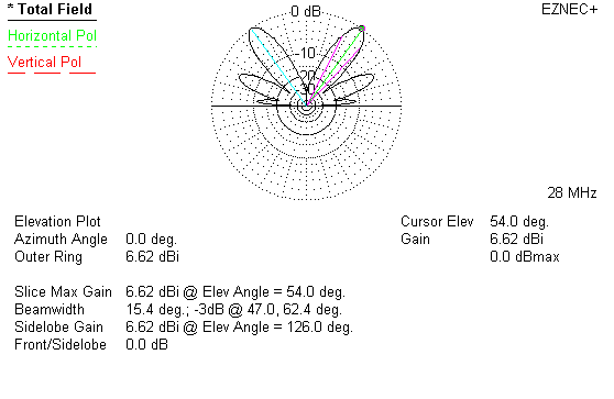
end-fe16.gif

(though to be fair the article in which this model is found in states "In this case I picked one of many worse-case feedline or mast lengths:" Which may not be the case with any given installation.

So the Solarcon GPK kit for the MAX2000 is not resonant (they are not long enough to be at 6ft, they fall short of 1/4 wavelength radials that a "normal 5/8 wave requires) so it will not likely reduce radiation angle. It may however keep some common mode currents off the coax. (when isolated from the mast)

I am wondering what to do to avoid those terribly high lobes burning holes in the Cumulo Nimbus.

Ahh.... that looks better... the article states: "This change is entirely the result of altering height and feedline/mast length!!!"
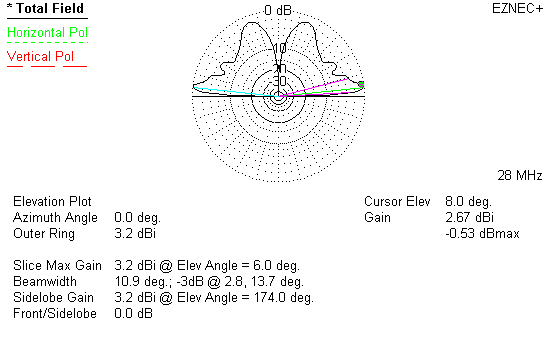
end-fe17.gif


The full article and details regarding the MAX2000 on this page, near the bottom:

http://www.w8ji.com/end-fed_vertical.htm

What is the guaranteed way to get those lobes as low as possible ?

I suspect the answer to be.. 4 x horizontal 1/4 wave radials (Maybe 2 is sufficient ?) with isolation from the metal mast. I guess I am looking for confirmation/consolidation of all the things I have read on the MAX2000.

It is very convenient to pop the MAX2000 on a pole, very easy to screw the 3 sections together and you are away. It would seem that to ensure the antenna is working well for DX might be less practical and less convenient.

Thanks
 
Last edited:
  • Like
Reactions: will c

There is one clarification I seek...

Is common mode current on the coaxial feeder different from "your coax radiating"

Or is it one and the same thing ?

When you measure how big 1/4 wavelength is (9ft approx) you realize.....

A) Why very few 5/8 waves ship with 1/4 wave radials.

B) Why people put up with all sort if problems/performance issues.

C) Why people use Gain Master's :LOL: (and why Sirio sold truck loads of them)
 
Last edited:
On the face of it a 5/8 wave ground plane-less antenna, with the dual coils/capacitor matching section at the bottom. I have been reading that feed line radiation is part of the antennas design with all the ambiguity that causes for radiation pattern, TOA of elevation lobes, SWR issues and common mode on the coax issues.

I have tried mine today on 20ft of pole(no choke, no balun, no nothing), local signal reports seem to be up ! Great. What does that mean for DX ? I don't know as yet cause the conditions were not good enough to find out. In reality this will take 10-20 DX session to get even the slightest understanding of performance. Given that I wish to understand how to get those TOA lobes down. Is this antenna acting like the cloud warmer like the images we can find for this ground plane less antenna ?

Ahhhhhhhrgggg, that looks terrible:

end-fe16.gif

(though to be fair the article in which this model is found in states "In this case I picked one of many worse-case feedline or mast lengths:" Which may not be the case with any given installation.

RadioDaze, I cannot tell the setup that produces the pattern shown, so I doubt the antenna setup you describe above will produce anywhere near the bad results shown in the model W8JI posted. I tried to reproduce the pattern shown with my Imax model, but no luck...there just isn't enough info in the article.

So the Solarcon GPK kit for the MAX2000 is not resonant (they are not long enough to be at 6ft, they fall short of 1/4 wavelength radials that a "normal 5/8 wave requires) so it will not likely reduce radiation angle. It may however keep some common mode currents off the coax. (when isolated from the mast)

I am wondering what to do to avoid those terribly high lobes burning holes in the Cumulo Nimbus.

Ahh.... that looks better... the article states: "This change is entirely the result of altering height and feedline/mast length!!!"

end-fe17.gif

I cannot reproduce this pattern either, so I doubt this pattern is a result of a simple altering of the height and feed line/mast length too.

The full article and details regarding the MAX2000 on this page, near the bottom:

http://www.w8ji.com/end-fed_vertical.htm

What is the guaranteed way to get those lobes as low as possible ?

The information in this article is very limited too. Not enough information to try and duplicate these results either. There is some information that gives some insight to possible issues with this antenna, but that is about it...you sure don't have enough to figure out the problems you anticipate.

I suspect the answer to be.. 4 x horizontal 1/4 wave radials (Maybe 2 is sufficient ?) with isolation from the metal mast. I guess I am looking for confirmation/consolidation of all the things I have read on the MAX2000.

It is very convenient to pop the MAX2000 on a pole, very easy to screw the 3 sections together and you are away. It would seem that to ensure the antenna is working well for DX might be less practical and less convenient.

Thanks

According to my Eznec models below the Imax, with 72" horizontal radials appears to make a little better gain than 108" radials. However, I do note that the model with shorter radials also appears to generate a bit more current on the mast, so in that case the 108" radials may do a bit better job on CMC's. I will have to make the slanted down version of radial on the Imax to see how those compare in modeling.
 

Attachments

  • IMG_0001.pdf
    213.3 KB · Views: 248
Last edited:
  • Like
Reactions: RadioDaze
It looks like a 5/8 or .64 wavelength design with a tip at 2.5 wavelengths above some kind of ground. That would explain that current distribution for w8ji's first image.

I cannot determine the type of ground under the antenna. He just states "real earth", which is about half of the info I need to duplicate the earth in his model. None of the ground types I have tried match the gain his model shows. The high angle lobe is easy to simulate to within a few degrees, as is the three lobe pattern, the gain range of similar looking models in the in 3-4 dBi gain range. I can get gain into the 4-5 dBi gain range, but when I do the lower lobes are different, like they are merging into a single lobe. I haven't gotten close enough to the 6.62 dBi gain of the high angle lobe, coming up more than 1 dB short in all cases I tried tonight.

I feel that it needs to be pointed out that this appears to be a worst case scenario. This is not indicative of an average install, and definitely not an install where the antenna feedline is choked, and the antenna is isolated from the mast...

Further, if he used the actual dimensions for the antenna, the antenna would have a significant higher angle lobe as it would be longer than is optimal for 28 MHz. Although, the exact length used in his model is speculation at best... That being said, if that were the case that could possibly explain some of what I'm seeing with the model, including the significant high angle secondary lobe in the lower version of the model.

I agree with Eddie, there isn't enough information to easily duplicate this result.


The DB
 
  • Like
Reactions: Marconi
I know some of you have done extensive modeling with eznec.anyone modeled with 5/8 th radials and 32 ft above ground?

Vk, I do a lot of my models at 32' feet to the feed point, and I've tried to describe why here on the forum. However, I don't think I've seriously messed with 5/8 wavelength radials that much, but I do remember a ham OP here in Houston writing an article and publishing it somewhere on the Internet.

He describes using 5/8 wave radials in an Eznec Demo model, and claiming a nice advantage in gain and maybe angle too...in his real world application as well.
 
Thanks for the very informative and knowledgeable replies. Yes I did bear in mind this is a worst case model in some manner so hopefully it is not as bad in my basic install.

I can certainly experiment with a choke, isolation and I have one of those MJF 1:1 RF line isolator as well.

I did not experience any negative influences in the "shack" i.e. the vehicle everything worked fine. And this was with no choke and no ferrite based isolator installed. Just tried it in basic set up. I found it interesting local reports for signal went upwards a little.

I did note the lowest SWR obtainable on T5 area was 1.4 to 1.5 : 1 Which I gather is about typical for the MAX2000.

I wish 1/4 wave radials were less cumbersome.

In an article that The DB posted regarding radials on 5/8 waves it states : " First, they are not resonant, so adjusting for resonance doesn't enter into the picture at all." Though from the table of radial lengths vs radiating element length at 146mHz it would seem 1/4 wave is a goal where practical.

I do wonder what gain 1/6th wavelength radials would produce. (Max2000 GPK kit 6 feet long each)

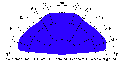
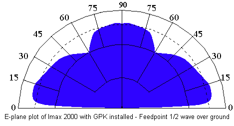
This article/forum post is of interest and seems to suggest a marginal improvement only by adding the GPK, though overall the plots/models over real earth at 20ft (slap bang where I have my antenna height typically) look very generous (Fantastic in fact !) especially compared to those very nasty high angle lobes I posted in the first post of the thread. I really cannot wait to get my teeth stuck in with the MAX2000 on the DX side.

Favourable plot 1/2 wave over real earth no GPK:

20448.gif


And with GPK:

20449.gif


Full article:

http://www.copperelectronics.com/discus4/messages/7750/20506.html?1023340740


So maybe I should plump for a IMAX GPK kit. I will have a think about that, so very many people say there was no differences at all. But maybe that was without mast isolation. new antenna additions are fun. I will operate the IMAX as it is for a while first and see how it fairs.

I do find it curious that the matching rings have no effects whatsoever on SWR from bottom to top of their thread. It makes me wonder if cutting a few inches off the top might bring the SWR down for 27.500. Though it says it is factory tuned for 27.205 and I never operate very far from there. Probably best to leave it alone.

To add : I am starting to wonder if the MAX2000 has a beneficial wide range of low angles for DXing. I recall the article on here suggesting that TOA is not the be all and end all. And that it is best to have a good range of angles being emitted for successful DX. This time of year the awakening DX favouring low angles of the F2 hops (as opposed to the Sporadic E layer hops that favour higher take offs)

A closing thought for this post : Maybe the Gain Master does have the technically lowest take off angle between the 2 antennas (when mounted in absolutely ideal conditions i.e. 1 wavelength and above which is hard for myself being a mobile static station) but maybe the general dispersion of the lobes from the GM is less advantageous for overall good DX. I don't know I am just running a train of thoughts in my head without access to professional test equipment. It will be interesting to start getting out and DXing with the MAX2000. (I hasten to add that RX noise floor is also of interest and I suspect that may be ever so slightly higher with the MAX2000, I can comment more on that with further experiences)

This interesting post springs to mind:

http://www.worldwidedx.com/threads/the-myth-surrounding-antenna-take-off-angles.140770/
 
Last edited:
Credit to bob85 for this, quoted from this thread...

http://www.worldwidedx.com/threads/mfj-915-installed-at-the-antennas-feed-point.188641/page-4

"The common mode impedance of your mast or coax braid is determined by their electrical length and equally as important them been connected to ground or not connected to ground,

1/4wave or odd 1/4wave multiples isolated from ground give low cm impedance & high cmc, = bad length,

1/2wave or 1/2wave multiples isolated from ground give high cm impedance & low cmc, = w8ji's lucky length

If the mast or coax are connected to ground the impedance is inverted, then we have a situation where,

odd 1/4waves invert the low ground impedance to give high cm impedance & low cmc, = another lucky length,

1/2waves reflect the low ground impedance to give low cm impedance & high cmc, = bad length

When you operate the radio from a psu you always have a path to ground through the mains earth or ground wire to ground rod & that forms part of your coax braid electrical length & resulting cm impedance "


(36 feet being one wavelength at 11m, 20 feet is just right and 27 feet would seemingly be not such a good choice without an isolator in line, I will skip the earthing of the mast next time)

This forum has such great information. Seems my 20ft pole (when unearthed) is a fairly good matched length for the MAX2000.
 
Last edited:
According to my Eznec models below the Imax, with 72" horizontal radials appears to make a little better gain than 108" radials. However, I do note that the model with shorter radials also appears to generate a bit more current on the mast, so in that case the 108" radials may do a bit better job on CMC's. I will have to make the slanted down version of radial on the Imax to see how those compare in modeling.


That would be very valuable Marconi if you have the time as I plan to make my own radials from 2.5mm copper solid core (plastic sheathed) cable.

This is 2.5mm UK main wiring cable, very similar to the USA 14 gauge wire the MAX2000 is manufactured from, I just strip out the blue and brown wires for antenna stuff.

images


The mounting bracket and fibre glass outer on the original GPK look quite impractical for a mobile static set up. (I am thinking antenna pole erection here with 6 feet long fibreglass radial springing around as I try and mount the plate to the antenna)

Whereas 4 x 72 inch copper core sheathed wires are easy for me to just bend up and keep stored on the antenna (also lighter). I will just solder these with a high power soldering iron onto some thick steel washers and fit them to the U bolts at feed point. Once I have the antenna partially off the ground on my swing hinge drive on plate I can start to position the radials into position.

I may not get the droopy angles 100pct correct but I hope this will not massively affect the performance.
 
Last edited:
So I lived and learned today. I put some 9 foot radials on the bottom of the IMAX soldered to washers and attached to 2 bolts (drilled holes in Max2000 base plate), one washer each side. Used reinforced ABS plastic tube. (foolishly reinforced with wood glue and a bit of wood, it was all I could think of/had laying around)

It looked pretty weird and the radials were larger than I initially thought and more dangley and more crazy lol ! I used 2 feet long...thin bamboo sticks to hold them in a cross approximately.

Once it was up 20 feet the ABS tube bent and it came down, luckily without issue to the MAX2000 the mast or me ! It remained attach to the ali poles thankfully. Better to find these things out earlier in the winter DX season I guess.

So not 100pct sure what to do right now.

I used the MAX2000 with a patch lead emanating from the SO239 and a MJF 1:1 isolator some extra ferrite 213 sized ferrite split clamp chokes after that on the main RG-213 down lead.

DX was weak but managed a special contact to one of the earth's least populated areas. 1,860 miles away from the UK. The Western Sahara.. Call sign 300 RCU-DX (Azman in Tifariti)

I think realistically I will use both the MAX2000 and the Gain Master this winter. There might be merit in this approach as each might allow DX to different areas based on slightly different take offs... maybe. We know this is complex and almost beyond our own choices and more to do with chance.

I now wonder whether to try again with the ground radials with some other isolator method (other than the ABS pipe, I saw some people use a wooden stake). Either way the radials are quite clumsy for a mobile static station and fiddly. Today was the first of the Autumn winds on the hill at around 30mph estimated. That made it hard enough, a taster of what is to come.

I have to balance my setups with safety and convenience and maybe take a slight performance hit on not having the radials (The differences in radiation pattern appear very slight anyway). I will think more and work out how to proceed with the MAX2000 in my set ups.

I may even just get the GPK kit and be done with, even though it is extra work building it and taking it apart each time (the 6 nuts). I will think it all through.

First I need to get a strong mast isolator worked out.
 
I can see it now. A switch in the mobile and 2 coax runs. One to the max2000 and the other to the GM!! LOL!! It will be a dxing static mobile for sure!!!
 
  • Like
Reactions: RadioDaze
The thought has crossed my mind, also co-phased verticals. But whilst the performance side is enviable I am always reminded of the practical implications of decisions made at home when I go out. Also I would need very long lengths of RG213 to run both so they did not interact with each other so i let that idea go for now. Every time I set up I might have forgotten something, lost something, have a technical problem to resolve so I have a box with a load of radio bits and bobs. There is a balance to be had performance vs set up implications.

It keeps it fun I guess.

As far as the IMAX I need to sort the isolation from the mast then I will try with shorter 6 foot radials. A compromise just like the Solarcon GPK is. And yet it appears at least to make a some small differences.

At least according to this quite old review: (What I do like is the 1/2 wavelength plots which is just about where I mount my antenna at lowest height)

http://www.copperelectronics.com/discus4/messages/7750/20506.html?1023340740

Also going to drill the U bolt holes out to widen them slightly and fit some metric size U bolts that are local to here then I can use butterfly wing nuts (UK ones do not fit US U bolt size) that make clamping it to mast quicker/easier. (I note the cylindrical ali section might make that tricky, stops wing nuts spinning on that side of the clamp, so will leave normal nuts on those U bolt threads)

So this is just a little set back.

The mast isolator bit is stumping me.

edited..... I found a wooden shovel handle that will fit perfectly.. I will varnish it up to protect against weather first. I can plane it if I need to shave some off to get it to mate nicely if required.

I want to give the MAX2000 a proper chance to hold up or beat the GM. If that can even be assessed at all. Either way I want it performing as well as it can given my set up.
 
Last edited:
  • Like
Reactions: 222DBFL

dxChat
Help Users
  • No one is chatting at the moment.