I’ve been reading a lot of information on how the variable knobs on Texas star amps are the weak link and are notorious for going out. With that being said , should one run the 667v full clock as well to bypass the resistors or does one need to use the knob on this amp to lower the carrier and get more swing ? Which would be safer on the amp as far as longevity ? Thanks guys

You are using an out of date browser. It may not display this or other websites correctly.
You should upgrade or use an alternative browser.
You should upgrade or use an alternative browser.
-
You can now help support WorldwideDX when you shop on Amazon at no additional cost to you! Simply follow this Shop on Amazon link first and a portion of any purchase is sent to WorldwideDX to help with site costs.
-
A Winner has been chosen for the 2026 July 4th Retevis RA89R Giveaway! Click Here to see who won!
Variable knob on 667v ??
- Thread starter Klint
- Start date
I believe the 667 is the only Texas Star amp where the knob is active all the time. This is from their site, " RF Output Knob controls RF output level when the Green Button is engaged. On the DX 667V only, the RF Output knob is operational at all times."
The way to run a 667 is don't over drive it, too much input dead key and peak drive watts will hurt the amp. Years ago with the one I ran I think the AM dead key on my radio was 1.75 watts. On SSB I used maybe 12-14 watts.
The way to run a 667 is don't over drive it, too much input dead key and peak drive watts will hurt the amp. Years ago with the one I ran I think the AM dead key on my radio was 1.75 watts. On SSB I used maybe 12-14 watts.

This is a video on how the deadkey effects output with a 667V. 0.5 watt to 1 watt is where I run mine. Anything over that is just creating heat and will shorten the life of the amp.
Was just concerned about where to put the variable on the amp. I have read where the variable was the weak link on TS amps . Does that apply to the 667v’s as well. If so then from what I understand , the best case scenario would be full clock on the knob, right.?
They are a the weak link in the chain for sure, so if you were to run with the variable turned down to try and control the output deadkey, that would most likely be the first point of failure.
Mine is an older amp (TURBO MOD TWO THIRDS KILOWATT) and it seems to have a much more robust potentiometer in it, but that may have been replaced before I got it as mine also has a sweet sixteen combiner in it.
Either way it is best to adjust the radio deadkey with the amp on high for about a 100 watt deadkey and you should be good to go.
I can't tell you how much I hate the "2 watt dead key rule" because in WAY too many cases, it's just too high.
Last edited:
VR1 100ohm POT 1W (667V only)
(Above from the CBTricks website)
Try replacing the potentiometer with a higher rated device and run it where you want to.
https://www.ebay.com/itm/2-pcs-5W-W...077915?hash=item521dc9ba1b:g:t24AAOSwkwJc-7x6
https://www.mouser.com/ProductDetail/CTS-Electronic-Components/026TB32R101B1A1?qs=sGAEpiMZZMtC25l1F4XBU9ebFVlJKl0pCMWfkdf3KyE=
73
David
Last edited:
I’m right at 2 watts carrier on a cobra 29. Looks to me like I need to set the carrier on the amp to dead key around a 100 watts with the variable knob on the amp and let it swing . Does that sound about right ? That would be on the high side I would assume.
No you need to have the amp set for full output, then adjust the dead key input on your radio until you see 100 watts out from the amp. Using the variable on the 667 to adjust down to 100 watts is how these burn up. Someone will have a radio that dead keys say 5 watts and then they use the variable on the amp to dial down to 90-100 watts out. That's too much input for that control to handle.
A higher-rated control sounds easy.
But every one rated for more than 2 Watts is a wirewound type. Acts like a resistor okay for DC and low AC frequencies, but not for RF.
RF energy will treat that control as if it were a tuning coil. Won't work correctly used in that spot. Even if you could make it fit. Most controls rated for more than 2 Watts are just too large.
I have seen that control wired for zero ohms when turned all the way to the right. A jumper across the two terminals that are connected takes care of the problem for those.
Other production runs had the control wired in parallel with the input to the driver transistor. Max power was also max resistance. A fixed 5-Watt resistor in place of the control is needed to preserve the input impedance for this version.
The two pushbuttons still give you decent control over the drive level. One of the four combinations they give you has always been close enough to match most radios. Most radios that are small enough in the first place.
Operating a 667 amplifier calls for a radio with a carrier control.
Period.
73
What I've done is...
Once you find a power level that is acceptable to the Amp and you...
We have two choices, you and I -
I'm only offering this because as those T/S age, (any Bi-polar amp really) the pots are harder to locate and their costs are going $$$ up and they have to accept the outputs of MOSFET's output radios become more the norm, you need to do this.
Else the older Bipolar to MOSFET conversions on a simple regular AM-Only (2078) or simple SSB with nothing more than a 16 watt PEP (2312 or 1969) setups are now replacing them with MOSFET, they are a little too much power PEP for the Amps to take like the older days of even a limiter-off full-bore Bi-polar breathing fire into the amps Input.
I mean, its' your money - but why throw it away in smokes?
Once you find a power level that is acceptable to the Amp and you...
We have two choices, you and I -
Keeping the Variable control
- Remove the pot, and install a FIXED divider in it's place (BEFORE the input reaches the board FROM THE POT (the Divider? There's a reason for that...)
- Install a BUFFER resistor of about 10 ~ 15 ohms at 2W rating IN series (In line) with the pot and it will act like a lower dead key variable.
- JMHO - this option is better for the amp - because it never sees peaked PEP if your radio was a MOSFET conversion with limiter removed, the potential power swings can throw the Amp too much peak power and damage those Bipolars...
- - you will wind up getting something like a 15 ~ 22 ohm 2W resistor in line with the feedline to the input (internal where the pot would be) - then attached ACROSS it at the connection to the board, is a 150 ~ 220 (2W) ohm BLEEDER resistor to ground (strapped) to again lessen the vari-key impact of swing into the amp.
- The Divider can be installed BEFORE or AFTER the POT, before it's TAPPED output goes into the board - so the POT sees more resistive output and NOT SINK all the wattage going into the amp
In regards to the Divider...
The Divider setup is more for MOSFET driving Bipolar Amp design...
Once you have decided to run FIXED NON-variable - this is when you have a Vari-key Mod like JP-36 and Swing Mod like NPC-RC at the radio and you just want the amp to be a set it and forget it...
If you're into Competition Comp Stomp stuff - then obviously this mod won't apply to you. Run it as you wish...The Divider setup is more for MOSFET driving Bipolar Amp design...
Once you have decided to run FIXED NON-variable - this is when you have a Vari-key Mod like JP-36 and Swing Mod like NPC-RC at the radio and you just want the amp to be a set it and forget it...
- You have to determine the level of drive but keep your Tech in the loop ok? Because they will need to know where the DIAL setting of the POT is so you can show them - I WANT IT HERE for BEST RESULTS
- They then can take out the pot, read the ohmic value, and install the proper resistive FIXED value and if needed in MOSFET converted radios - a BLEEDER resistor of a higher ohmic value (See Above) of same wattage (2W) is attached and applied across the input from the output end of the Buffer resistor to ground to remove a lot of the PEP drive that can get those Bipolar units hurt and fail fast...again only for those MOSFET Finals' to Bi-polar amps.
- - you can then run your SSB levels (if so equipped) or Mic Gain (Dynamike) as you see fit to drive swing into the amp
- - you will wind up getting something like a 15 ~ 22 ohm 2W resistor in line with the feedline to the input (internal where the pot would be) - then attached ACROSS it at the connection to the board, is a 120 ~ 150 ohm BLEEDER resistor to ground (strapped) to again lessen the vari-key impact of swing into the amp.
- In this setup you no longer have the Variable at the Amp, your variable is at the Radios Power settings and swing methods of power delivery - BACK AT THE RADIO. Your amp has been swamped with some resistive elements to reduce the dynamics of the radio from potentially damaging your amp when you get careless or too drunk to care - which if you're prone to that type of activity - is BOUND to happen.
In That Case...
- Just ask yourself - "Why if I'm here for Full Throttle Action - why do I need a Variable?" - and act accordingly.
I'm only offering this because as those T/S age, (any Bi-polar amp really) the pots are harder to locate and their costs are going $$$ up and they have to accept the outputs of MOSFET's output radios become more the norm, you need to do this.
Else the older Bipolar to MOSFET conversions on a simple regular AM-Only (2078) or simple SSB with nothing more than a 16 watt PEP (2312 or 1969) setups are now replacing them with MOSFET, they are a little too much power PEP for the Amps to take like the older days of even a limiter-off full-bore Bi-polar breathing fire into the amps Input.
I mean, its' your money - but why throw it away in smokes?
Attachments
Last edited:
Just a FYI for anyone looking at the Potentiometer that is listed above from mouserVR1 100ohm POT 1W (667V only)
(Above from the CBTricks website)
Try replacing the potentiometer with a higher rated device and run it where you want to.
https://www.ebay.com/itm/2-pcs-5W-W...d=link&campid=5336136228&toolid=20001&mkevt=1
https://www.mouser.com/ProductDetail/CTS-Electronic-Components/026TB32R101B1A1?qs=sGAEpiMZZMtC25l1F4XBU9ebFVlJKl0pCMWfkdf3KyE=
73
David
do not use this item as it is a wire wound version.
The variable on the amp limits total RF input to the driver (1st) stage. It does not control carrier level. Your radio does that.
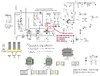
Since this post started no one has mentioned the new 667V.....
The new 667V has two IRF520 MOSFETs to take the place of the 2SC2290 which used to be the driver (1st) stage.
The variable control is wired a little differently, but I've had no problems with mine and I use my variable all the time.
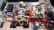
It is not my amp, I got this picture from the internet.
The picture doesn't quite show variable control wires but shows some mods that were done to this amp.
A lot can be done to make them better, besides putting fans on them. The main thing is to make sure that the output combiner doesn't get warm or hot, meaning a balance problem between the two boards.
The new 667V has two IRF520 MOSFETs to take the place of the 2SC2290 which used to be the driver (1st) stage.
The variable control is wired a little differently, but I've had no problems with mine and I use my variable all the time.
It is not my amp, I got this picture from the internet.
The picture doesn't quite show variable control wires but shows some mods that were done to this amp.
A lot can be done to make them better, besides putting fans on them. The main thing is to make sure that the output combiner doesn't get warm or hot, meaning a balance problem between the two boards.
Attachments
dxChat
- No one is chatting at the moment.