Yes I have a varmint XL 600 and it looks almost brand new it’s still had the rivets in the bottom when I turn it on all the tube light up The receive preamp works but when I key no power at all the relay does not even click so I opened the bottom and found a gray wire not even hooked up by the filter capacitors on the power supply the other end of the wire goes to the board I believe it says B+ on it Whenever I tested the voltage of that wireGet rid close to 950 V can you please tell me where this wire goes

You are using an out of date browser. It may not display this or other websites correctly.
You should upgrade or use an alternative browser.
You should upgrade or use an alternative browser.
-
You can now help support WorldwideDX when you shop on Amazon at no additional cost to you! Simply follow this Shop on Amazon link first and a portion of any purchase is sent to WorldwideDX to help with site costs.
-
A Winner has been chosen for the 2026 July 4th Retevis RA89R Giveaway! Click Here to see who won!
Varmint XL-600
- Thread starter 88_bandit_88
- Start date
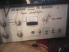
Nice amp. What exactly does the other end of that wire connect to? Is there any way to see the other side of the board?
Last edited:
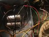
The only way to see the other side of the board is to remove it the grey wire I’m asking about is on the same trace as the yellow one on the bottom right of the board and the yellow wire I believe goes to a relay
88_bandit_88,
Below is a link to CB tricks on the Varmint XL150-XL450 power supply. I would imagine that the XL600 is very similar. The only thing I can think of is that your grey wire (showing close to 950 volts as you said) is the wire labelled "B+" in the schematic. You will have to trace it back through the rectifiers and capacitor bank to be sure.
http://www.cbtricks.com/Amp/brewer_labs/graphics/xl150-xl450_power_supply.jpg
If your grey wire is indeed the "B+" wire, you can follow the link below to attach it properly. It appears that the "B+" wire from the power supply section attaches to one of the common terminal of the relay(s).
http://www.cbtricks.com/Amp/brewer_labs/graphics/xl150-xl450_sch.jpg
Again, the links above apply to the XL150-XL450. It may not be 100% correct. Use your best judgement.
BE SAFE!!!!! PUT THE POWER PLUG IN YOUR POCKET, DISCHARGE THE CAPS AND BE SAFE!!!
Good luck!
73's
David

I'm pretty sure that wire end goes to the positive lead of the "top" of the series string of three fat filter caps.
I'm accustomed to tracing a wire, back to the other end before making this kind of decision.
It's hard to make out the parts mounted on the power-supply circuit board just to the rear of the blower motor. They face away from you on the upper surface of the board. The far end of the loose wire should connect to the cathode (band) end of two rectifier diodes on that board, the bridge circuit for the HV.
The positive lead of the cap you want for this connection will have ONLY a bleeder resistor already connected to it. If you see a wire on the positive end of one of these caps, it's the WRONG one of the three.
You want the one that has a bleeder resistor and nothing else connected to it's positive lead.
73
Nomad,
It would be nice to know if 88_bandit_88's "close to 950v" measurement on the grey wire is AC or DC. If DC I would think it to go to the common relay terminal. If AC, should feed the rectifier/filter caps.
Quite the puzzle. I have very little info/schematics on Varmints.
73's
David
It would be nice to know if 88_bandit_88's "close to 950v" measurement on the grey wire is AC or DC. If DC I would think it to go to the common relay terminal. If AC, should feed the rectifier/filter caps.
Quite the puzzle. I have very little info/schematics on Varmints.
73's
David
If memory serves, there is one set of three series-connected filter caps on the HV supply, hiding on the other side of the power-supply pc board. Those will filter the HV bridge rectifier's output and get you a proper DC voltage reading, even with the other string of three filters out of the circuit.
The three caps mounted on tie strips under the transformer are in parallel with the set on the power supply board.
Smaller models would use only the caps on the power supply board. This model needs the additional filtering, in parallel with the ones mounted out of sight on the power-supply board.
73
Smaller models would use only the caps on the power supply board. This model needs the additional filtering, in parallel with the ones mounted out of sight on the power-supply board.
That's good to know Nomad. I had no idea about the additional caps underneath (or in this case, on top!)
I haven't had my hands in a Varmint in probably 20 years-and I think it was a XL150.
I'd make a mental note of this info-but afraid I'm out of paper!

Good Luck 88_bandit_88. Let us know how this turns out for you.
73's
David
Well... ok this is what I would do:
The circuit board needs to come out to verify what this grey wire is connected to. This is needed to verify that it comes from the high voltage rectifier. Without knowing this, there is no way to be 100% sure. You shouldn't have to disconnect any wiring, just unscrew the mounts and flip it over for some pictures. I hope you don't think I am trying to make you do a bunch of stuff that is un needed, the only other way would be if someone were to have a picture of the exact same unit to verify. We want to be sure that we are giving you the best information we can.
Chris
88_bandit_88,
I noticed in the first picture of post #3 of this thread that the "neutral" (white) wire of your 120v power feed has gotten too close to a soldering iron in the past. This may be the time to carefully inspect it and repair if necessary.
73's
David
I noticed in the first picture of post #3 of this thread that the "neutral" (white) wire of your 120v power feed has gotten too close to a soldering iron in the past. This may be the time to carefully inspect it and repair if necessary.
73's
David
dxChat
- No one is chatting at the moment.