Still cannot get the keying circuit figured out it is literally driving me nuts!! Any help would be awesome

You are using an out of date browser. It may not display this or other websites correctly.
You should upgrade or use an alternative browser.
You should upgrade or use an alternative browser.
-
You can now help support WorldwideDX when you shop on Amazon at no additional cost to you! Simply follow this Shop on Amazon link first and a portion of any purchase is sent to WorldwideDX to help with site costs.
-
A Winner has been chosen for the 2026 July 4th Retevis RA89R Giveaway! Click Here to see who won!
Varmint XL-600
- Thread starter 88_bandit_88
- Start date
Okay, so a quick recap of what I remember from this thread is that the keying circuit worked until the keying transistors got replaced, along with the electrolytic caps on the power-supply circuit board.
I remember suggesting that you put all the original keying circuit parts back exactly where they were when they worked.
But if you didn't make a detailed diagram of which transistor lead went into which hole, that probably isn't practical.
There are several wrong ways to insert a 3-legged transistor into a circuit board, and only one correct way.
But I may be skipping the important part.
Do you have 12 Volts DC on the main relay's coil terminals when you select "operate" on the standby switch?
If you don't have power to the relay, the keying circuit can't do anything whether it's wired correctly or not.
Let's assume for the moment that you do have power to the relay, and the keying circuit just won't.
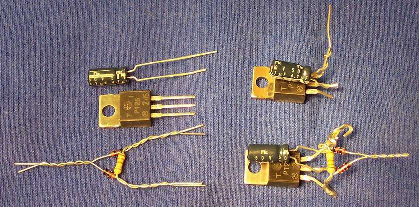
Here's a shot of the assembly procedure for the circuit we use. Got tired of hand-building them like this, so we build it on a tiny circuit board now.
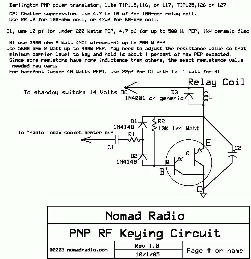
Here's a crude schematic of it. The CAD I used did not have a symbol for a darlington transistor, so I made one.
Sorta.
The metal tab of the TIP125, 126 or 127 transistor is simply bolted to ground. A wire goes from the emitter lead to the 'cold' side of the relay coil, opposite the side of the relay coil that goes to the standby switch. The emitter is the one with the hook on the end in the final assembly step seen above.
Never could figure out how to make a buck selling this thing for less than 30 bucks. Considering the low cost of the parts, should be no big deal to build.
Just make sure that you DO have power to the relay coil. Could be that you broke a foil on the power-supply board when replacing filter caps.
73
I remember suggesting that you put all the original keying circuit parts back exactly where they were when they worked.
But if you didn't make a detailed diagram of which transistor lead went into which hole, that probably isn't practical.
There are several wrong ways to insert a 3-legged transistor into a circuit board, and only one correct way.
But I may be skipping the important part.
Do you have 12 Volts DC on the main relay's coil terminals when you select "operate" on the standby switch?
If you don't have power to the relay, the keying circuit can't do anything whether it's wired correctly or not.
Let's assume for the moment that you do have power to the relay, and the keying circuit just won't.
Here's a shot of the assembly procedure for the circuit we use. Got tired of hand-building them like this, so we build it on a tiny circuit board now.
Here's a crude schematic of it. The CAD I used did not have a symbol for a darlington transistor, so I made one.
Sorta.
The metal tab of the TIP125, 126 or 127 transistor is simply bolted to ground. A wire goes from the emitter lead to the 'cold' side of the relay coil, opposite the side of the relay coil that goes to the standby switch. The emitter is the one with the hook on the end in the final assembly step seen above.
Never could figure out how to make a buck selling this thing for less than 30 bucks. Considering the low cost of the parts, should be no big deal to build.
Just make sure that you DO have power to the relay coil. Could be that you broke a foil on the power-supply board when replacing filter caps.
73

Now the amp will key but when it’s on high it won’t unkey really about to just give up on this old varmint and also people said there is a bad hum in my audio so yeah. I replaced all six filter caps so that should’ve took care of the hum I would think????
If it only holds itself keyed in High side, that suggests that the amplifier is oscillating, creating its own RF signal when the radio unkeys.
The keying circuit can't tell the difference between the radio's RF and the internal RF an amplifier produces when it oscillates.
Does a wattmeter in line with it show power when it's holding itself keyed in High side?
That would settle the question.
If the driver plate tune control is "touchy" or erratic, this would suggest you have a stability problem.
For that matter, if turning any of the tuning knobs will cause it to unkey on High side, this would settle this question right there.
73
88_bandit_88,
If you have the keying problem solved, you probably do not have an oscillating problem. I think Nomad's response was that oscillation could keep the relay keyed.
Hum problem:
1. double check placement of all electrolytic capacitor polarities.
2. Any electrolytic capacitors not replaced? (Smaller size and values usually responsible for relay keying and receive pre-amp duties should be replaced as well)
3. Rectifier diodes installed correctly? Recently replaced? (If not, should be replaced. Pretty heavily taxed with new capacitors-especially if values were increased above stock)
Trimmer Cap:
More than likely alters input tuning SWR to the driver tubes. (I'm not looking at the schematic at the moment) Adjustment may change the "erratic driver tune control".
Take these hints with a grain of salt if you wish.
Nomadradio is THE "Tube Amplifier Guru". I'm just an old man that has had some experiences. Some good and some not so good.
Good luck!
73's
David
Yes I replaced all the rectifier diodes for that matter everything but the resistors have been replaced on the HV Power Supply board. Still has a hum in the audio transmitted could it be the Ohmite: Z-14 Axial Leaded High Frequency Inductor?
There is a small 56 uH RF choke in line with the grid-bias wire for the drivers, and another one between the final tubes' control grids and the wire that leads to the "High/Supermod" switch.
They are easily damaged if a tube breaks down. Or if a tube has previously broken down in the last 40-odd years at least once.
This causes oscillation problems, if it overheats inside and burns the varnish off the tiny wires wound inside the choke. Causes the adjacent turns of the coil inside to short together. They look like a small resistor, with axial leads (one out each end) in a cylindrical package the squared-off ends, usually.
A continuity check won't tell you if a choke is shorted inside. But if either of them looks as if it has been hot, that's a hint.
And if you have an inductance meter, that's the quick way to tell if one of them is bad.
73
There is a 10watt resistor in line with the supermod switch I don’t see a choke everyone on the radio says it has a bad hum in my audio man I wish I could find out what is causing it
If you have a look at the voltage on one or the other of the two grid-bias RF chokes, you'll probably see rectifier ripple riding on the negative DC bias voltage. Gotta move the 'scope baseline to the top of the screen to do this.
If there is too much 120-Hz ripple on this voltage, it modulates the radio's carrier. And as you turn down the carrier power on the radio, it gets louder.
And if you don't see more than a half-Volt or so of ripple, the problem is elsewhere.
I looked for a bench file on this problem, and don't see one. Gotta dig out the old Varmint folder and see if we have any diagrams that aren't on CB Tricks. Might, might not.
73
After a moment's thought, it penetrated that you probably have the newer version, with all the tube sockets mounted on a big pc board.
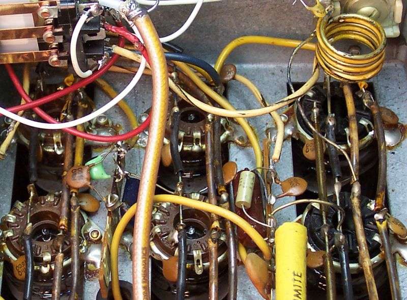
Only pic I have showing grid chokes is from the original version, with the tube sockets mounted to the chassis deck, and wired point-to-point. The driver choke is the gray tubular part just to the left of the middle driver-tube socket. The final-side grid choke looks different, lighter green It's been replaced with a substitute.
To find the grid chokes on the top side of the pc board, find a foil trace that joins together pin 2 on each driver-tube socket. Might also have pin 8 connected to pin 2. They will lead to a tiny axial-lead RF choke like the gray one to the left of the middle driver-tube socket, just above the yellow Z-28 choke.
The final grid choke will have one end connected to a trace that ties together pins 5 and 9 of each final-tube socket.
Haven't found a pic of that.
Damage from a tube surge may be visible, may not. Only way to be sure is either measure the inductance, or substitute one that you know is good. If there is no change, that wasn't it.
The grid choke on the final tubes fails more often than the one on the driver tubes.
73
Last edited:
Dear mr nomad i got a 350 xl varmint has a broken drive tuning capactor have hard time finding 1 the 1 says mc 50 pf. Dont know witch 1 work does it matter voltage i was able to find 1 but its 200 voltsI do hope the original AC power plug is still intact.
It's a product called the "Eagle" plug. Has two fuses inside it. It saved Abe the cost of putting a fuseholder inside the amplifier.
But nothing lasts forever, and that plug was made from some fairly-brittle brown bakelite plastic. Any time the AC cord or plug gets replaced you MUST add fuse protection inside the amplifier. Running one of these with no fuse is risky.
73
dxChat
- No one is chatting at the moment.