
RF final 35.19
Rf final base No volts
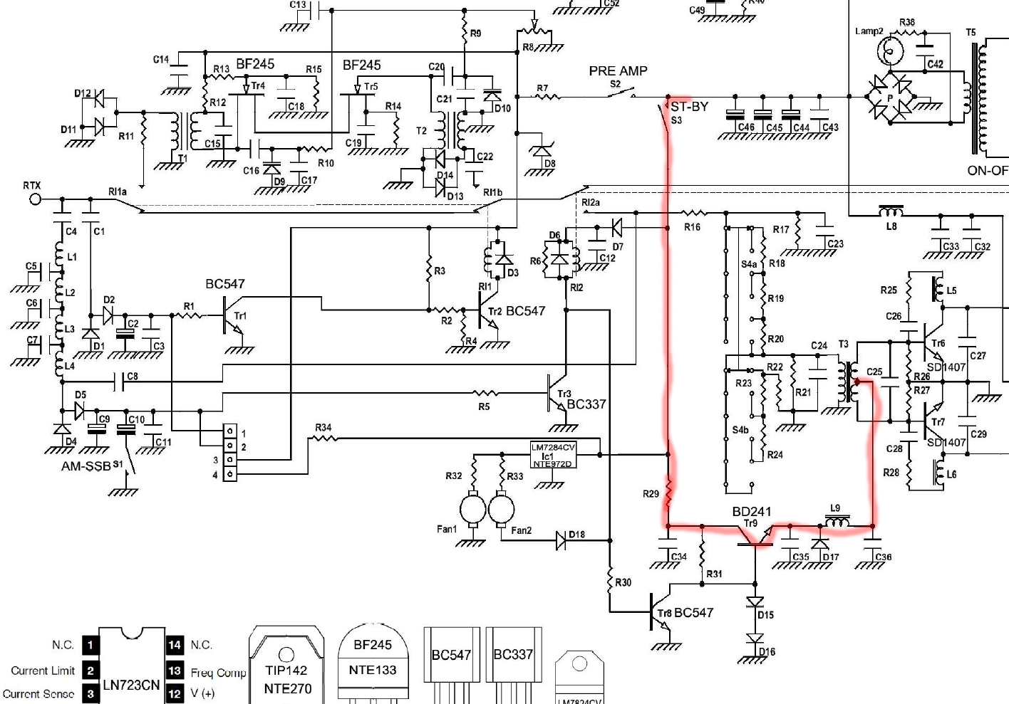
all legs of of TR9 no volts amp power on in standby
supply voltage 13.21 keyed and unkeyd
base tr8 unkeyd .752 volts keyed no volts
R29 35 volts on standby switch side no volts on c34.... R29 shows 1 ohm
C34 shows ground on both sides
Rf final base No volts
all legs of of TR9 no volts amp power on in standby
supply voltage 13.21 keyed and unkeyd
base tr8 unkeyd .752 volts keyed no volts
R29 35 volts on standby switch side no volts on c34.... R29 shows 1 ohm
C34 shows ground on both sides
Last edited:

")