• You can now help support WorldwideDX when you shop on Amazon at no additional cost to you! Simply follow this Shop on Amazon link first and a portion of any purchase is sent to WorldwideDX to help with site costs.

A Palomar 300A in distress

Dmans

Sr. Member
Jan 22, 2017
1,471
1,961
173
Georgia
My everyday amplifier started showing some signs of needed some attention about a month or so ago. I have been kind of busy and took it out of line and used a back up amp for a while. Curiosity got the better of me so I took the covers off this past weekend to see if I could find out what was ailing it.
This amp is pretty much all factory aside from the two main filter caps being replaced (not by me) at some point in the past. It has 6-6KD6 tubes (maybe original?) in it. I had the cover off of it 1 time since I have owned it (about a year and a half). It has been mainly used behind my TS440 on the "Low" setting. With 60-75 watts input, it showed 450-475 watts output on SSB. It has occasionally been used behind my 139XLR on the "High" setting. With 20 watts input, it showed 550-600 watts output on SSB. All reports were the signal was clean but recently I had reports the audio was "fuzzy" and noticed output was climbing to near 900 watts! Oops, time to shut it down.

Below are a few pictures of what I have found when opening the case.

Clean face. (Not a fan of the plastic toggle switches)
DSCI0437.JPG


Underside of RF deck. (No signs of previous work aside from the filter caps)

DSCI0438.JPG


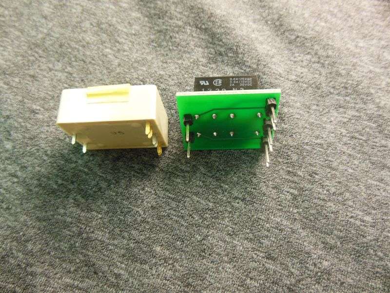
You can see the white wire is frayed and has been hot. It was pinched under the edge of the circuit board along with the 2 coax cables-for years! The wire comes from the upper left terminal of the Cinch-Jones plug (total of 3 wires on that terminal) I believe it to be 1 of the 12vac feeds from the transformer which is later rectified and applied to the control grid of the driver tubes.

InkedInkedDSCI0439_LI.jpg


I will be working on this in the near future and since it is my "everyday" amp it may get a lot of new parts!

Stay tuned.

73's
David
 

Since the TS-440 has 100 watts drive so no need for a low drive amp required, why use an amp like this where the tubes work very hard and soften up quickly? 100 watts can easily drive a pair of 3-500's to 1500 watts and they will be very comfortable at that level on SSB and will handle way more on AM than a few sweep tubes. Even a pair of 572B's will run 900 watts PEP on SSB. A couple of 572b tubes are probably less to buy than a half dozen other sweep tubes.
 
  • Like
Reactions: tecnicoloco
Um, just to start, those three white-plastic 1000uf 25-Volt electrolytics have to go. They tend to fail as a short, causing unnecessary grief. When they fail open, you get hum on the output signal, or a keying circuit that gets squirrelly.

Either way, they can't be trusted. Not a question of if they'll cause trouble, but when they will.

And if one of the two bias filters at the lower-left in the pic go bad, you lose grid bias. Might make the power take a hike upwards and cherry the tubes.

Next item would be to make sure the screws that provide a ground connection at the corners of the pc boards are tight. Palomar used plastic spacers to support the pc boards. Heat will cause them to shrink, and loosen those ground screws.

Poor ground connections are a good way to make the amplifier unstable, producing fuzzy modulation.

One thing we learned to do to this model is to replace the coax that leads from the High/Low switch to the cathode circuit of the final tubes. It gets hot where it runs alongside the four final tubes. Eventually the center wire migrates through the polyethylene dielectric and shorts to the shield braid inside the coax. Makes it dead, no power either in High or Low side. We use thin teflon coax to replace it. Won't have that problem again with that fix.

That's what I would check first, anyway.

73
 
Um, just to start, those three white-plastic 1000uf 25-Volt electrolytics have to go. They tend to fail as a short, causing unnecessary grief. When they fail open, you get hum on the output signal, or a keying circuit that gets squirrelly.

Either way, they can't be trusted. Not a question of if they'll cause trouble, but when they will.

Loud and clear on the white plastic capacitors. All electrolytics will be replaced minus the 2 main filter caps. They were replaced shortly before I acquired it.

And if one of the two bias filters at the lower-left in the pic go bad, you lose grid bias. Might make the power take a hike upwards and cherry the tubes.

There are 4 "cement" resistors (I call them) at the lower left. 2-27ohm 5 watt and 2-50ohm 10 watt. They will be replaced as well. I tend to replace resistors rated 2 watts and up. Can't be trusted after 40+ years.

I have replaced the old coax in some recent "upgrades" I have done for other folks recently. The coax that was pinching the 12vac wire from the transformer has a foam dielectric. Never have liked that stuff! In my experience it doesn't "play well with heat". I have used RG-313. It has a Teflon dielectric, is small and holds up to heat well. (A real space saver too!)

Some people may ask why I fool with these sweep tube amps. For me they are a great cheap learning tool. Yes, sweep tubes can be hard to come by, but I have found that if the tubes are treated right and not pushed hard, they will give good service. Not unlike a 70's car or truck with 100k miles, these amps will require a "tune-up". To me this means replace all electrolytics, all rectifier diodes, all higher wattage resistors, cleaning relay contacts, flux removal from traces as well as a close inspection and repair of questionable traces, resoldering high voltage traces, replacement coax jumpers and (sometimes) new SO-239 connectors too.

This particular amplifier kind of "fell into my hands" for $125.00 and was working great. I don't know of anywhere else you can get 1/2Kw for that kind of money. I believe it to be well worth the investment to "renew" this classic!

If my operation of a sweep tube amplifier offends anyone, please place me on your ignore list.

Nomad,
Thanks for the tips on this one. I last owned one of these in 1979 and I think it is a great classic piece to restore!

73's
David
 
Last edited:
The bias circuit needs to have a fairly low resistance to ground. This is the current-return path for the tubes' grid current.

A variable-bias adjustment would need to have several Watts' dissipation rating, just as the fixed-bias resistors do that it's built with.

There's not a lot to be gained from this. 40-plus years ago radios just didn't have carrier-power controls, and adding this feature to an amplifier made sense.

If you radio already has this control, the amplifier won't benefit from having it added.

Consider also that those bias-adjust pots in the 350Z would repeatedly blow out and have to be replaced. Was one of that amplifier's most-aggravating weak links in the design.

73
 
I've noticed the driver stage in this amplifier is susceptible to the side effects of secondary emissions. That is, it keys at one level and after you modulate for a few seconds, the power can rise by as much as 200 watts. Lesser quality or weaker tubes in the driver stage can cause this amp to behave like this because the screen grid already does not have a low enough resistance to ground as Nomad mentioned. This amp just uses a resistor but it works fine when used with great tubes. The use of a shunt regulator reduces these issues and often allows the tubes to be used much longer before instability appears.

I'm not saying that is what's wrong with this particular amp, but if the problem persists, you might consider temporarily swapping the driver tubes for a pair of finals and see if you notice any improvement. 6LF6 driver tubes seem less prone to this and some 300A's came with them in the driver. If they aren't all matched, be careful this swap doesn't cause some to turn red when keyed a while. Everything Nomad said needs to be done first. Those white caps are almost never good anymore. If the PC board screws are still tight, it's only because someone re-torqued them within the last decade. Note that these screws have nuts on the top and bottom of the chassis. The screw head must make a tight connection to the PC board ground before the nuts lock the screw up.

Years ago it was a fair argument to favor the 572B or 3-500Z over sweep tubes just based on tube life alone. Since Cetron and Eimac stopped making these and they are all made in China now, things aren't the same. The old Cetrons in my FL-2100 lasted 20 years when the new Talors lost full output within a year. Four RCA 6LQ6 made in 1968 are still running strong in an old Dentron. One Eimac 4-400A made in 1963 peaks 1500 watts with a 375 watt carrier in a T-368. Point is if you need glass that will last, buy NOS.
 
Nomad and Shockwave,
Thanks for your responses. I am just looking at options for this amp. Since I plan to replace most every electrical component in it (including wires) I wasn't sure if there weren't proven improvements that can be done to make it last another 40+ years.

The little ferrite beads are still on the driver tube plate cap leads (not sure if there ever were any on the finals?) but I had planned to add some 47ohm 2watts with a 4 turn coil for each plate cap lead (and leave the ferrites in place-suspenders and a belt thing).

My thinking is most every manufacturer of this era left out a couple "5 cent" parts here and there to improve profits or that would have made a major improvement in the behavior of this model. Since tube radios were the norm when this was built, can improvements be made? Can I make the amp more friendly to transistor based equipment and correct some known oddities about this model.

I'm not concerned about adding the left out "5 cent" parts. As little as I have in this amp, it deserves a serious freshening up and a few circuit changes or parts value changes along the way is not a problem or concern.

73's
David
 
The ferrite beads that Palomar used as parasitic chokes looked like a cool idea when I first saw them used in the 300A around 1976. Ferrite beads were still a new technology 43 years ago, and this looked like a logical way to use them.

Then I started seeing the broken fragments of them rolling around inside the bottom cover after the amplifier was used for a while.

Oops.

Turns out they don't take the heat very well. They fracture and fall off. These days it's more common to find the plate caps on the four final tubes with only a bare wire between the plate choke and the plate cap of each final tube. We adopted the policy of installing the conventional resistor with four turns of wire on each final plate connection. Haven't seen one with the ferrite beads still in place for a long, long time now.

Not sure why, but the two driver tubes almost always have the conventional resistor-type parasitic choke installed at the factory. Makes me wonder if the factory didn't trust the ferrite beads for the driver stage.

It's a surprise to see how many of these amplifiers are stable without that parasitic choke on the final tubes. Just the same, it's bad policy to assume the amplifier will behave properly this way. And if the tubes get changed, the next set may or may not behave as well without parasitic chokes. Just safer to put them in there.

73
 
Repairs have begun on my 300A. There is no easy way to access the circuit traces on the high or low voltage boards other than to remove them from the chassis and no easy way to remove one board at a time. Talk about cramming 5 lbs of s#^t in a 2 lb sack......
Since the trouble began with a pinched 12vac feed to the low voltage board, that is where I chose to start.
Below is a picture of the low voltage board after removal from the chassis.

6E5BC3B9-62F5-4C81-9FA0-3F525CB8E79A.jpeg

3E87EA91-BEF9-41F1-AFC8-173AB79605F0.jpeg


I removed all components and wiring, cleaned up the crusty flux and installed all new components on the board including new wiring.

Below are pictures of both sides of the board after overhaul.

FE0ACD77-71AF-4E8B-AD00-FE80D80762FB.jpeg

The small wires in the picture above were the original wires. I believe they are 22ga. I replaced them with 16ga with Teflon insulation. I am hopeful that replacement of the old RG-58 foam coax with RG-313 will make enough room for the larger wires

7214DED2-6A55-4999-AE8A-3E0881EF4CD1.jpeg


Stay tuned.
73’s
David
 
More progress has been made on my "Everyday" amp. It has been slow going lately with little time after my real job but nonetheless, there is progress.

Below is the relay board after replacement of the diodes, resistors, the keying and Pre-Amp transistors and the SSB delay electrolytic capacitor. Also visible are the 4 leads of RG-313 coax on the lower left of the board. These replaced the 40+ year old RG-58 foam. The RG-313 has a Teflon inner dielectric and is 1000 watts capable-or advertised as such anyway. I have had no problems with it in the past. Also visible on the lower right of the board are supply and control wires. I used Teflon insulated 16ga wire to replace the original 22ga wire. I left the leads long and will trim to fit when reinstalling the board.
DSCI0452.JPG


Next up is the high voltage/rectifier board. I used 1N5408 rectifiers on the high voltage side and the 12v side. (I pay the same for them as a 1N4007-so why not?) These require enlarging the holes in the board slightly but is easily done with a pin vise drill. The extra capacity of these diodes makes it a no-brainer. Although they are larger physically than the 5406's that I removed, they still fit nicely with a slight re-routing of one filter cap leg. I also prefer that they "stand up" off the board for cooling purposes.
The wiring was also changed to 16ga in place of the standard (and wimpy) 22ga.

DSCI0456.JPG

DSCI0457.JPG


While these 3 boards were out of the chassis, I was able to do some much needed cleaning after its 40+ years. Also replaced the S0-239's while access was much easier.
DSCI0459.JPG

DSCI0460.JPG

DSCI0461.JPG


Next up will be removal and renewing of the driver and final tube socket boards. Those boards will get the same treatment-replacement of resistors, 1-electrolytic capacitor, cleaning/removing flux and re-soldering of leads/tube socket pins and replacing a few jumpers on the boards.

Stay tuned!

73's
David
 
An update to the 300a refurb. The relay board is back in the chassis and mostly wired up. I removed the board for the driver tube sockets and replaced the components I intended to replace as well as a couple of jumpers on the board.
A1E4AAEF-40E4-4C01-AD01-B7D321A10904.jpeg

Looking closely at the tube socket pins this afternoon I spotted a potential problem that needs to be addressed now while it is torn down this far. There are several “cold solder joints” around the tube socket pins. The circuit board holes for the pins are quite a bit larger than the pins themselves but there are visible “halo’s” around most of the pins.
75F93386-22D1-40CC-8C9E-3F8CA463D859.jpeg


The picture below is of one tube socket already repaired.
1F3C5F27-1F99-42DF-821B-662A822701B9.jpeg


One more tube socket to repair and then I will see if I have the patience today to wind a couple of 4 turn coils for parasitic suppressors around 47 ohm resistors.

Stay tuned.

73’s
David
 
If either or both of the white-plastic "R50" relays has gone bad, we have a drop-in solution for that one. NOS replacements pop up on fleaBay and tend to be pricey.

The date code on both is early 1976. They might both still work okay.

If they don't, cleaning only helps sometimes.

This is what we use.

RCoCdA.jpg


They're on fleaBay.

73
 
Nomad,
I tested them on the board with a power supply hooked up (prior to the board installation. dang tight squeeze in this chassis!) to the relay board-so far so good!
Thanks for the tip. I will keep it in mind.

Turns out I only had enough patience to wind 1 suppressor and it turned out shorter than I wanted. Maybe another go at it tonight.

73's
David
 

dxChat
Help Users
  • No one is chatting at the moment.
  • dxBot:
    Tucker442 has left the room.
  • @ BJ radionut:
    LIVE 10:00 AM EST :cool:
  • @ Charles Edwards:
    I'm looking for factory settings 1 through 59 for a AT 5555 n2 or AT500 M2 I only wrote down half the values feel like a idiot I need help will be appreciated