• You can now help support WorldwideDX when you shop on Amazon at no additional cost to you! Simply follow this Shop on Amazon link first and a portion of any purchase is sent to WorldwideDX to help with site costs.

Booty Monster's Vector 40000 thread on Eham

Except the gain has been determined in CST and published by Sirio at 2dbd. Every field test I've been able to participate in confirms this gain and even more when I change out a side mounted dipole to this design top mounted with no tower interfering with the pattern. The evidence is there for those willing to see. One can assume Sirio is not being truthful but this is not Solarcon claiming 9.9 dbi on an Imax. Claims like that don't stand in the field. What Sirio claims is repeatable in the field.

PS: Dale has not posted any more info.

Well Donald, I can't argue your numbers.

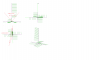
Do you think the 2 dbd numbers were over real Earth with or without a mast, or in free space?
 
I don't see a significant difference if 2dbd is measured in free space or over real earth. Once the antenna is over real earth there is added gain from the ground reflections. So long as the Sigma is compared to the dipole at the same height above real earth, the Sigma should still come out close to 2 db over the dipole. Because the phase of the cone on the Sigma is in phase with the top 1/2 wave, this also means any currents descending on the mast will also be in phase up to a 1/2 wavelength down from the connector feedpoint. Contrary to what W8JI says, the performance of this antenna improves with mast and coax as a result of this.
 
so it has 42 - 45 ft of in phase radiation ?
does a 1/4 wave or a 1/2 wave have any in phase radiation on the mast below the feed-point ? don't those antennas become out of phase at or slightly above the feed-point ?
 
here is a brief review of another one of sirio's sleeve antennas with the same claimed 4.15dbi/2dbd gain vs a 1/2wave,

The Four Metres Website

I purchased one of these a few years back and scaled it to the same frequency to test it against the Sigma design. The CX series definitely does beat a 1/2 wave dipole but I was not able to get it to match the gain of the Sigma design. There are two major differences between the designs. Obviously the base of the CX is not tapered but it's parallel to the vertical radiator inside. The second difference is the CX does not use gamma matching even though the specs say it does. There is no adjustable capacitance in the matching network like in the Sigma. This forces you to set the radiator length to provide the needed capacitive reactance to match the antenna since inductive reactance cannot be canceled in the matching network itself.

The Sigma produces maximum gain when the radiator is tuned around .82 wavelength but this wavelength cannot be made to look like a resistive load without adding capacitive reactance in the gamma match to cancel the inductive reactance of the radiator. We then have to compromise the gain by adjusting the radiator length to provide the match. There is always a trade off when designing antennas. To get one thing, we usually have to give up another. Gain is one thing I don't like to compromise with and will go the extra mile to give something else up before gain. In this case the trade off is power handling or size of the gamma because its capacitive properties are beneficial in this match.
 
  • Like
Reactions: 1 person
a forum member sent me some pics of a cx antenna,

SirioCX4-1.jpg


i agree the gamma allows us to get a good tune with a wide range of monopole lengths, we are not stuck with 3/4wave in order to have significant current in the monopole above the sleeve like the skeleton sleeve monopole,
i also agree you are right in the ballpark of what length works best;)
 
eh..marconi,

stop reading this thread you have several emails :))

Regards, H>
(first back to work)

I saw the emails Henry, but I didn't understand much. The results you sent me used some other modeling program that I've never seen before.

I tried to figure it out, but I didn't think it helped me explain why the 5/8 wave Eznec model I sent you does not indicate a phase shift in the tabular currents log for wire #2, like the model does when the Currents are turned on in the Antenna View.

I will continue to study the work however, but what does the image below tell me about Eznec.

View attachment Henry's idea on phase.pdf
 
Shockwave, I heard from Dale and they did not have a chance to do the Sigma4 project this week end. He said it might be about 6 months before he gets settled in at his new home.
 
That picture is showing a phase angle between 0 and 170 degrees.
I was under the impression the question was:
....where do those angles come from, how is it possible that we only "read" o to -170 where you are expecting them to go from + through "0", beeing negative and and up at "0" again at the top of the antenna.

If one looks from above at the antenna the phase angle goes from 0 to -170 degrees just like eznec says..
Your looking to the side of the antenna and expecting the angle to be "o" at the center of the antenna
......its a bit more 3D ...
Does that sounds logical ?

of to bed now..didnt do much work hihi.
 
I was actually all ready in bed....

I think i have an "easy" way of explination.
its not entirly correct but migth help to visual what that 170 degrees is doing in your data.

Take a look at the tower of pizza (in italy)
Its a very tall building and its tilted to the left or rigth....depending where your standing i guess..(nevermind)

It has a stair around that going up all the way up. (twisted stair..like some fire escapes)

Now...just imagine that radio wave wanting to go to the top of the tower.

Now, what you are discussing is the angle how much the tower is tilted to the left (or rigth).

but there are more "degrees":

If we take a look straigth at the top of the pizza tower...

if that radiowave starts at the beginning of that stairs its at 0 degrees.
It starts "climbing" going around the tower and find it self higher in that tower though at 0 degrees again (at least if your above your starting point)

back to bed again...bussy day tomorrow...

Regards, H>
 
Henry, my question is not about how the phase image is displayed in Eznec Antenna View. With the 5/8 wave Eznec shows the out of phase condition at the base correctly in the Antenna View.

Here is another way to show a phase image of a 5/8 wave where we see the base in red being out of phase with the top 1/2 wave element. I have no question about how Eznec shows phase in the Antenna View.

View attachment 5_8 wave showing phase.docx

My question is why doesn't the tabular currents log below agree and indicate the phase shift correctly in the data for the radiator wire #2. See second image of currents log in the PDF file below where I note: "no phase shift noted"

View attachment Showing phase problem.pdf
 
Eddy...

And i was actually happy with the "tower" of pizza explination hihi...

Im not sure how to explain how i think it is otherwise..
I believe you are thinking a bit to much 2d where 3d information is provided.

The angle you have provided is not the angle of the red wire...
Well yes it is...but then looked from above..not side ways.

please see the attached.

Does it make sence in this way ?

(ps the provided antenna is your I-10K showing only phase (under different angles) in all circumstances.
its "twisted"...)

Regards,

Henry
 

Attachments

  • eddie angle.png
    eddie angle.png
    18.3 KB · Views: 4
I suspect that Henry is on to something with respect to understanding what the Eznec antenna view is saying when interpreted using the tabulated data.

I think that Eznec does not view the crossover of the red line as a phase shift as one might see with two transmission lines parallel, but interprets the cross over as an expected currents behavior for the 5/8 vertical, therefore seeing it as in proper phase to the antenna's length.
Add the V4k cone, or the open sleeved cage to the bottom of the antenna and you will see Eznec interpret the currents behaviors as what is consistent with transmission line behaviors.

The spiral view from above that the model Henry supplied tells us what is being reported on by Eznec - current that appears in the Eznec antenna view (2D) to be opposed, but are not because of the linearity of the current along the length of the vertical as seen in the spiral (3D) view.

Just thinking out loud.
 

dxChat
Help Users
  • No one is chatting at the moment.