• You can now help support WorldwideDX when you shop on Amazon at no additional cost to you! Simply follow this Shop on Amazon link first and a portion of any purchase is sent to WorldwideDX to help with site costs.

Booty Monster's Vector 40000 thread on Eham

Phase is a part of the current distribution profile. I have no idea how it looks in real life, we can't see currents. So we produce imaginary images of how currents might look, and that is what we have seen here.

I agree there are several ways for us to create images for the 5/8 wave radiator being out of phase at the base. After I posted Henry's image using a different program, I made this very point on posting another image using An-SOF...showing an an image of my I-10K model out of phase.

Y'all are missing my point though.

My issue with Eznec is not about the Antenna View image with Currents turned on.

I want to know why I don't see the same phase condition reflected in Eznec's tabular current log in this I-10K model I sent Henry.

In the pdf file below is a "Skeleton Sleeve Fed" model, and the last image shows the tabular current log. As an example of Eznec showing correct phasing in both the Antenna View and the tabular current log, please note that wire #1 indicates correct phasing with the words "phase change" for the model.

View attachment The Skeleton Sleeve Fed Monopole.pdf

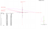
Here is the model I sent Henry showing the tabular current log in error compared to the Antenna View.

View attachment Showing phase problem.pdf
 
Last edited:
If possible ...Send me the skelton sleeve files eddie.


I am under the impression we do understand Eddy
Ill try to think of another way...

In my understanding your trying to interpertate the redline as a function of "phase" only.
Where it is not... its current and phase combined...
However in the written log you will find current and phase seperated from each other.

I look at it as taking a corner in the snow.
You have your steering wheel under a angle...but due to the snow the expected circle your making is much larger..hence a different angle/magnitude.

The file is on its way.

DB, if you're interested and want a copy...email me at edromans@comcast.net and I'll return you a copy.
 
I don't know how to supply you the answer, only my speculations.
However, I was addressing exactly what you asked. I may be way off,
but I was addressing the issue of Eznec tabulating or not the apparent
phase shift in the graphic. I said it appears that Eznec does not interpret
the seeming phase shift as a phase shift.
Perhaps Henry's answer has something to do with it.

Henry said:
In my understanding your trying to interpertate the redline as a function of "phase" only.
Where it is not... its current and phase combined...
However in the written log you will find current and phase seperated from each other.

sCo_idk.gif
 
I don't know how to supply you the answer, only my speculations.
However, I was addressing exactly what you asked. I may be way off,
but I was addressing the issue of Eznec tabulating or not the apparent
phase shift in the graphic. I said it appears that Eznec does not interpret
the seeming phase shift as a phase shift.
Perhaps Henry's answer has something to do with it.

sCo_idk.gif

Homer, I see this issue a little different. In the case of the Skeleton model, I see everything looks as we would expect...an obvious phase shift in the Antenna View and the same indication in the currents log. But, with my I-10K model the same is true for the Antenna View, but the tabular current log does not look to interpret this phase shift as you say.

Don't be confused by the bottom of the antenna showing up at the top of the list of wires in the currents log. I made a note of this on one of the current logs.

So, I wouldn't say categorically:
Homer said:
...that Eznec does not interpret the seeming phase shift as a phase shift.
 
I'm just adding some thoughts to the dialogue. I do not think I know anything for sure.
However, to me it is quite clear that Eznec is not interpreting the data presented for the I10k the same as you are expecting.
 
Shockwave, I heard from Dale and they did not have a chance to do the Sigma4 project this week end. He said it might be about 6 months before he gets settled in at his new home.

Eddy, that's not Dale responding to you in the other forum about testing the Sigma. Dale is already sure the Sigma is just a half wave. This of course makes me wonder how much Dale's 2 meter stick on the glass antenna team knew about Herb's work at Avanti research and development?
 
me thinks these folks that keep saying it's a half wave antenna would quit saying it's a half wave antenna if they put a half wave and then a vector on the same mast and feed line and compared their tx/rx results .......... ;)
 
me thinks these folks that keep saying it's a half wave antenna would quit saying it's a half wave antenna if they put a half wave and then a vector on the same mast and feed line and compared their tx/rx results .......... ;)

No, some of them insist they have done just that and couldn't detect any improvement. After doing this so many times successfully with the fussy clients I have, I think some that claim its just a 1/2 wave may have tested it and for one of many reasons they might have overlooked, came up with less than desirable results. Some may even be going as far as to have never tried one even though they say they have and just feel so strongly that it's only a 1/2 wave, they will tell you anything. Neither one effects the positive results I see everyday.
 
well, im on the same level as you homer.
my remarks here are just a thought.
It would explain things. But im not sure it is entirly corect.

Anyway, ill try to find more "proof".
And ofcours search in other directions as well.

Together we will find it.

othet "thoughts" are welcomed of course..

First work, cu guys tonigth.
 
Hello Guys,

Well....now attached a drawing with the 5/8 wave provided by marconi.
It shows the "current-phase" and the "written log".

In my opinion this is how things are.

Please let me know if the question is answered...and if it makes sences.
Ill try to get confirmation from Roy.

For you to "see" (marconi/shockwave) look at the "top" of the antenna and "enlarge" currents..

Kind regards,

Henry
 

Attachments

  • angle phase current 5.8 wave.png
    angle phase current 5.8 wave.png
    30.4 KB · Views: 7
Eddy, that's not Dale responding to you in the other forum about testing the Sigma. Dale is already sure the Sigma is just a half wave. This of course makes me wonder how much Dale's 2 meter stick on the glass antenna team knew about Herb's work at Avanti research and development?

I think you're right Donald, but this Dale did offer to do testing, so I followed up. I didn't realize that however, so thanks.
 
I'm just adding some thoughts to the dialogue. I do not think I know anything for sure.
However, to me it is quite clear that Eznec is not interpreting the data presented for the I10k the same as you are expecting.

That's fine Homer. I'm with you and I don't think I know anything for sure either.

I also believe my I-10K model is not indicating the phase shift in the currents log like we see with the Skeleton Sleeve model either.

So I wonder why, and that is my question regarding Eznec.
 
Whatever tool Henry used for the model above does not show a phase shift for the antenna, either.
It appears that the program views the current in a manner similar to the spiral model he produced before, and the tabular data is showing everything in the same phase except for the junction between the GP wires and the vertical.

So, once again, apparently Eznec defines the behavior of current along the vertical as typical of the antenna, but not as a phase reversal for an antenna longer than a 1/2 wave with GP radials.

And if it isn't a inverse phase, what is it?

Maybe it requires a cone or sleeve/cage along the lower vertical to cause Eznec (and other) programs to define the current behavior as a phase shift.
And maybe that's part of the reason why modeling Programs see the currents on the outside of the V4k/S4 as in phase.

I see the program accepting the idea of inverse phase occurring between the GP radials and the Vertical the same as with the two ends/sides of a dipole, but not on the same side of the poles at the same time. Maybe a model of the I10k with the GP radials also 5/8 wavelength might show the same behavior on each side/half of the antenna as it shows on only the vertical half of the antenna. . .

And maybe what we see in an extended vertical is something similar to a null (or series of nulls) on a very long wire antennas and not a phase shift at all . . .

Thinking again and possibly sounding a little daft.
 

dxChat
Help Users
  • No one is chatting at the moment.
  • @ BJ radionut:
    BLACKOUT HF
  • @ BJ radionut:
    I am beginning the packing process...XENIA bound Going "Lite": this year....2 items for sale...Rig #1 = FT-920/Gud to Ex condition/Hand Mike/pwr cord/manual (NO BOX) ... #2 = My 1 owner FT-950....EX condition...Original Shipping Double Box/Factory Manual/Never used hand mike...Booths 9107-9111...Ya'al come by say hello...
  • @ BJ radionut:
    Incoming Region Produces X3 Solar Flare
    May 15, 2024 @ 14:55 UTC
    Another major solar flare, but this time from an active region just beginning to turn into view off the east limb. It is possible that the group responsible is old AR 3654 from the previous rotation. The latest flare, an X2.99 event just peaked at 14:38 UTC (May 15). Stay tuned