• You can now help support WorldwideDX when you shop on Amazon at no additional cost to you! Simply follow this Shop on Amazon link first and a portion of any purchase is sent to WorldwideDX to help with site costs.

Booty Monster's Vector 40000 thread on Eham

Whatever tool Henry used for the model above does not show a phase shift for the antenna, either.
It appears that the program views the current in a manner similar to the spiral model he produced before, and the tabular data is showing everything in the same phase except for the junction between the GP wires and the vertical.

So, once again, apparently Eznec defines the behavior of current along the vertical as typical of the antenna, but not as a phase reversal for an antenna longer than a 1/2 wave with GP radials.

And if it isn't a inverse phase, what is it?

Maybe it requires a cone or sleeve/cage along the lower vertical to cause Eznec (and other) programs to define the current behavior as a phase shift.
And maybe that's part of the reason why modeling Programs see the currents on the outside of the V4k/S4 as in phase.

I see the program accepting the idea of inverse phase occurring between the GP radials and the Vertical the same as with the two ends/sides of a dipole, but not on the same side of the poles at the same time. Maybe a model of the I10k with the GP radials also 5/8 wavelength might show the same behavior on each side/half of the antenna as it shows on only the vertical half of the antenna. . .

And maybe what we see in an extended vertical is something similar to a null (or series of nulls) on a very long wire antennas and not a phase shift at all . . .

Thinking again and possibly sounding a little daft.

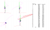
Homer, the image in Henry's post #72 above is the I-10K model I sent him, and he is using his Eznec Pro/4 to work it...a far advanced version of Eznec than I use. Thus the current data noted is the same as my model, or he cut/pasted the data I posted earlier. He also displays the antenna from the top view looking down at the tip. This is exactly what he tells us.

Concerning the spiral model Henry posted earlier. I asked him to explain how that related to Eznec and my question about the tabular currents log not showing a phase shift (reversal or inversion), but he has not answered.

I think his spiral type image is likely a 5/8 wave radiator using another modeling program, and it just happens to represent the phase by extending lines out from the radiator to a point similar to the red line using Eznec. It does not indicate the red line curve however, but I think this is basically what his model is showing us and it does look to indicate an out of phase area at the base...that looks to be a phase shift that is similar to Eznec.

Henry is still thinking my question is about the image, and not about how Eznec indicates the phase and current in the tabular currents log for wire #2, in this case.

You might be right that Eznec needs the radials slanted up for it to show the phase reversal in the bottom where we expect, but my models of my Sigma4 and my Vector show different results in this regard, and they don't support such an idea. That said however, I don't know why this happens, and I have tried to figure out why the S4/V4 show phasing and currents differently when using Eznec, unless this all is a simple error in modeling someway.

This is why I had the thought to use a different program, but I've only had it for about a week. IMO An-SOF is basically a colorful antenna simulator, and is not as intuitive for me. It looks to be far more technical than I understand, and the manual is very limited.

There is a very good starter tutor on YouTube however. Search for An-SOF. It starts with a simple dipole model.
 
Marconi:

Seems your question “enhances” ?

I quote: Your questions:

YOUR QUESTION:
I can't always be sure, but sometimes I see the model with current phase turned on indicating one thing, and the tabular current log showing another.
(AND:)
In words, this describes a 5/8 wave model where the Antenna View of the red current indicator with currents turned on, shows a phase change in the radiator just as we would expect. However, when we check the tabular Currents Log in the Currents View...there is no indication of this current shift.

END OF YOUR QUESTIONS

MY answer:
No, the tabular current log is exactly describing what is going on. and is exactly as the red current phase line indiactes.
The second part of your question is also incorrect. It does show...
END OF MY ANSWER.

Your Question:
The point I was trying to make to Shockwave was that Eznec showed the I-10K, 5/8 wave model's tabular data report incorrectly for some reason by indicating there was no cross over noted in the data. However, the Antenna view showed the phase shift correctly for this 5/8 wave model as noted above.

MY ANSWER:
----but there clearly is. The angle goes from rather low angle to 165 degrees at maximum magnitude going futher towards 170 with almost no amplitude.. THERE IS A CROSS OVER POINT !...Its at 90 degrees….however you have to stop thinking that it needs tob e at 0 degrees…its 3D.
END OF MY ANSWER>

Your Question:
My question is why doesn't the tabular currents log below agree and indicate the phase shift correctly in the data for the radiator wire #2. See second image of currents log in the PDF file below where I note: "no phase shift noted"

MY ANSWER:
Well the tabular curent log does agree…you are just interperating the red line wrong.
END OF MY ANSWER.

YOUR QUESTION:
Henry is still thinking my question is about the image, and not about how Eznec indicates the phase and current in the tabular currents log for wire #2, in this case.

MY ANSWER:
Well yes, but dont blame me…I am really trying those two do combine of course.
Stop looking to the side of that red line….look from above and enlarge current.
END OF MY ANSWER>

YOUR QUESTION:
Concerning the spiral model Henry posted earlier. I asked him to explain how that related to Eznec and my question about the tabular currents log not showing a phase shift (reversal or inversion), but he has not answered.

MY ANSWER:
Its important to understand phase and current are different things.
You can have a 180 degrees phase shift. BUT if there is almost no current it is difficult to “spot”. So what i did in the “spiral” thing…was to show you “only” phase…(indeed !)
MY ANSWER:

Your last question is rather easy:
Eznec indiactes the phase and current in the tabular current log with a amplitude and a angle.


And well…i know there are sirio enthousiast...heck im one of them
Good price/quality figure.....

BUt
Regarding sirio …well in the past i have seen some “rigth” advertising but sadly these days
Im afraid I'm not sure if i believe any claims of sirio…
Since they advertise with a 3el having almost 11 dBI and a 4el having over 13 dBI..
Just take a look at the website.
With that said.....i honestly doubt if 2dBD is truthfull.

Regards,

H.
 
Here is the Skelton sleeve....
Its the same antenna under differnt angles.
It shows exactly as eznec says.

Now...bare in mind the "long" red line indiacted by the applied red lines.
is only a segement !
Due to a magnification of current and due the different phase angle it seems rather large if one looks at it.

You have to sit down...
and just have a "brigth" look at it.

The written eznec log aswell as the current-phase indicators are telling exactly what they should tell ! They are equal.

Regards,

H/
 

Attachments

  • skelton sleeve.png
    skelton sleeve.png
    39.4 KB · Views: 4
I asked him to explain how that related to Eznec and my question about the tabular currents log not showing a phase shift (reversal or inversion)

. . . my question is about . . . about how Eznec indicates the phase and current in the tabular currents log for wire #2, in this case.
I believe where you are getting stuck is that you expect the tabular data to indicate a phase shift by using a - (minus) sign at the point of shift from data that has no sign.

Henry says it is there, but must be seen like this:

Henry said:
MY ANSWER:
----but there clearly is. The angle goes from rather low angle to 165 degrees at maximum magnitude going futher towards 170 with almost no amplitude.. THERE IS A CROSS OVER POINT !...Its at 90 degrees….however you have to stop thinking that it needs tob e at 0 degrees…its 3D.
END OF MY ANSWER>

He sees it not in the numbers having minus or positive signs on them, but by the data expressing itself by other indications.
 
Here is the Skelton sleeve....
Its the same antenna under differnt angles.
It shows exactly as eznec says.

Now...bare in mind the "long" red line indiacted by the applied red lines.
is only a segement !
Due to a magnification of current and due the different phase angle it seems rather large if one looks at it.

You have to sit down...
and just have a "brigth" look at it.

The written eznec log aswell as the current-phase indicators are telling exactly what they should tell ! They are equal.

Regards,

H/

Well Henry, your statement above noted in red is a real revelation, because this is exactly what I've been saying.

When I first posted about this Eznec current and phase issue, and frankly ever since too...I've been saying, apparently in vain, that this Skeleton Sleeve model looks correct in both the Antenna View and the tabular current log. I have no problem with the Skeleton Sleeve Fed model.

I simply supplied you with the Skeleton model as an example to show how Eznec can get the currents and phase correct. :headbang

I agree with you here, "...exnec is telling exactly what they should tell !"...as you say, regarding the Skeleton model.

Henry, how hard is it to understand...that it is the 5/8 wave model that shows the problem in the currents log...I've been talking about. The 5/8 wave model is the model I've tried to call to your attention?
 
Thanks for the reply Marconi,

Its not difficlut to understand..
I get it...and have tried to explain.

On the previous page i already showed (your) 58 wave.

And again, they "both" are equal.
The written log and the information displayed in the antenna view that is.

attached again the information.

let me know if you "see" it.

Perhaps a extra word could help.
The current phase you see are from the same antenna in both options.
one is from the side, and one from above.

But as already mentioned you have to stop looking for that 0 degrees and expecting it to be where you think it is....

Look more to the segments and watch where the difference in angle is large.
enlarge currents and rotate the model.

A antenna current and phase is not 2d "flat" to a antenna.
Its ""circulair" around that antenna. and that circle is expresed in degrees
where the change of phase can be noticed due to the large difference in degrees between segments....
.....the angle is not in the "vertical"ax..but in the horizontal ax.

as usual...

off to bed hihi

Regards,

H. 19sd348


ps homer....spot on !
 

Attachments

  • angle phase 58 wave.png
    angle phase 58 wave.png
    30.4 KB · Views: 6
  • Like
Reactions: 1 person
I have to admit I've been following this phase discussion and it's making little sense to me. Phase changes along the length of the radiator not from the side angle you are looking at. It's the length of the radiator from the source that determines the phase.

Perhaps I'm missing something here but I can tell you for sure that EZNEC does not get the phase correct on the Sigma design and that is easily proven when constructing a collinear version.
 
I believe where you are getting stuck is that you expect the tabular data to indicate a phase shift by using a - (minus) sign at the point of shift from data that has no sign.

Henry says it is there, but must be seen like this:

He sees it not in the numbers having minus or positive signs on them, but by the data expressing itself by other indications.

Yep Homer, that is pretty much what I think should happen at this point...the (+ -) signs indicate phase differences, and I believe the current log should reflect the lower portion of the 5/8 wave is out of phase with the top 1/2 wave. I would expect the signs to be different...similar to what we see in the Skeleton Sleeve Fed model.

Note the image below from Maxwell's Reflections II, that the currents on the elements of the dipole are in phase...going in the same direction. The feed point of a center fed dipole does not show a perfect match with the feed line, so we see indicated some common mode currents flowing on the outside of the feed line due to the difference, and thus we have a lack of balance and symmetry. But if the feed point matched the feed line perfectly...then the dipole would radiate without common mode currents. So Homer, you'll see how the sign of the phase follows the rules noted above.

Reflection II Sec 23.1.jpg

We're familiar with the idea that feed line currents should not radiate when the line shows equal magnitude and opposite phase (direction). In this case it is due to feed line cancellation which is desirable.

I use this issue about feed lines and the Maxwell's dipole as examples of the cancellation idea. This is similar to the cancellation I see at the base of the 5/8 wave radiator, where the phase signs should be noted to be different due to part of the radiator being out of phase. I can't be 100% sure, but this is what I think.

Here are two Eznec models of a simple dipole. Both models have the phase turned on. I tricked one to show it to be out of phase for this post. You will see that Eznec handles this correctly, but as you will also note even tough we see this problem that defies the cancellation theory, so-to-speak, this does not ill-affect the gain, pattern, or match as best I can tell. If you check the tabular currents log for either model, segment by segment, you will also see a little difference in the current magnitudes. This small difference will be reflected as CMC on the shield of the feed line. This example is how I see this issue and wonder.

View attachment .50 Wave dipole currents.pdf

As far as I'm concerned this is not a big deal, because my buddies likely care less about antenna currents in modeling, but in Shockwave's case, trying to satisfy some regulation or patent requirement for his antenna business, he probably found this issue the very Eznec thing that gave him his problems.
 
Last edited:
@shockwave,
Thanks its good to know the effort was not for nothing.
Without having looked at it...im pritty sure it should provide accurate readings with collinear antennas. Could you share your file with me over the mail ?

And for what its worth....reading your answers... i value your experience a lot more than i do compared to "data" provided by sirio.

@ Marconi,
You have to know by know im not good of a "between the words" reader.
If i may ask, are "things" understood? or do you still have problems to interpertate.
I am more then willing to phone you if needed and sit down for a couple minutes.
We migth evan arrange a sked on 11 with these kind of prop hihi.

Kind regards,

Henry
 
Last edited:
@shockwave,
Thanks its good to know the effort was not for nothing.
Without having looked at it...im pritty sure it should provide accurate readings with collinear antennas. Could you share your file with me over the mail ?

Henry, EZNEC has done a good job modeling just about every collinear antenna I've tried except the Sigma. If you build a collinear Sigma in EZNEC it will show maximum gain with the phasing section 100% longer than what works in the field.

That is a huge miscalculation that strongly suggests to me that EZNEC is not accounting for the radiation in the cone because the phase is off by the exact 90 degrees worth of radiation in the cone.

Sharing my model won't help to confirm the error in EZNEC. That will require building the antenna and field testing it. Only then will you see that the 180 degree phasing section that works in EZNEC is a complete flop in the field.
 
I have to admit I've been following this phase discussion and it's making little sense to me. Phase changes along the length of the radiator not from the side angle you are looking at. It's the length of the radiator from the source that determines the phase.

Perhaps I'm missing something here but I can tell you for sure that EZNEC does not get the phase correct on the Sigma design and that is easily proven when constructing a collinear version.

Shockwave, I don't understand how Henry's idea about phase relates to my question either. He and I just weren't connecting with our words at times.

Eznec displays their phase idea as a 2d image, and when I switch the phase ON for the model, the red line indicating magnitude and phase for the currents for this 5/8 wave radiator...look just like I would expect. I was never concerned about the phase image in the Antenna View, and I think Henry misunderstood the specific point of my question.

I can't say Henry or Homer are wrong however, when they see in their minds eye that the phase is flowing around the radiator. So maybe there was some confusion. I've had similar experiences many times.

Well I was about to go to bed and I had a thought from God...for how I might fix my I-10K model. Wa la, now the phase in the Antenna View and the tabular currents log agree, and they're working together just like I would expect. They are working just like I've seen in my other models where phase seemed obvious and for sure with my collinear models.

I have attached both models below to compare. The first model is correct, and the last model is the original...showing the currents log in error as I tried to point out.

View attachment I-10K no matcher 18' fixed.pdf

You may recall that I have, for some time, questioned how my Vector/Sigma4 models don't work like I expect in the phase part or at least they look to work differently. Now I'm going to apply this same modeling fix to my Vector model, and I hope it results in being closer to what Sirio publishes for gain on their New Vector 4000, that it shows the proper phase shift, indicates a good Average gain result, and produces some radiation from the cone area...as you and Bob have been telling us.

If it works out like I expect, I'll email you two guys the file.

Here's praying.
 
Marconi,

You do realize that changing the phase anlge of the source wont provide the influence you are hoping for.
(for the readers...that will change the number of the angle provided in the current log...but not the angle between them.)

The same effect can be seen with a different coax length.
(that will also change the "angle number.....NOT the angle it self)

In aspect to your last PDF:
Take a look at segmentation number 5 and 6 of both data provided.
In your "correct" model and in you "no phase" model showing "error"....

IN BOTH MODELS THERE IS A 40/50 DEGREES CHANGE....
THERE IS NO DIFFERENCE BETWEEN THEM.

However, you keep reffering in rigth/wrong and in terms like current log error.
There is NO error. Both are rigth
Think more in terms like at segment 5/6 thats where your "phase shifts" is.

You have to stop looking for that phase shift at 0 degrees.
A phase "change" happens there where the amount of angle changes really fast.

Now, im afraid you still have difficulties interpertating things, that has nothing to do with me not understanding you.
I think that due to remarkts like this:

EXAMPLE:
"You say with "your fix" the antenna view and tabular current long agree..
But how else can interpertate that ...it seems to me you fail to realize they ALREADY agreed.

EXAMPLE:
Your last PDF ...the "fixed" one...
You provide two "data" one is the tabular current log and the other the current - phase indicator as provided on the "view" antenna screen.
However ...THOSE TWO DO NOT COMBINE. Well...they do but not as you want to express the angle of the phase.
They will if you look from above...If you got it...Why would one provide the not logical view ???

ANOTHER EXAMPLE:
Your expectation in regards to your "fix" and your "wish" it will change the vector.
(for example: you mention your hope the gain beeing closer to the one sirio provided)
The expectation (hope) alone you have... says enough.

Ask yourself...
What you have done is similair to removing the source directly from the antenna and place it at at the end of a quater wave coax cable.
now, would it mather if we changed the angle of the source ?
Were at 27000000 Hz active (27 Mhz,) it happens rather often per second..

Now, im perfectly understanding that you would like to put it under "miscommunication"
But, I honestly believe that is not the case.

Now, im afraid my effort explaining you is not producing the result i have hoped for.
(except for shockwave/homer and a few other readers perhaps)

Oh well, you cant have all :)

Kind Regards, H.
 
Last edited:
@ Marconi,
Pse see my new post to you at the end of page 11..


@ Shockwave:

.....when you say...."i have to admit"..."it's making little sences...
Would that be: you understand a litlle...Or not ?

If not...
Of course phase changes along the length of the radiator....
And thats why the angle is expressed along the (in this case) vertical and thus heigth...segmentations.

However the single angle provided is given from a "above" view".

I understand its difficult to see....but one has to "think" 3d...instead of just looking in 2d against that vertical wire.

So its more or less a vector....
At first we have the "heigth" of that wave. (along the radiator)
At that height there is a certain current with a magnitude...
And that maximum magnitude at that point can be pointed in a specific direction (under a horizontal angle).
At thats the current phase angle.
Its "cruled"...twisted...

So, yes it is logical that with heigth the angle changes.

However the angle provided is not given with a magnitude point of view.
Most people look to much at the magnitude of that line...and "see" it going through the ax of the antenna.
But that says nothing about the ANGLE...it only shows there is no magnitude.
THe angle could be a lot of things.

It is provided at a "single" segment heigth...and therefor horizontal (in this case)

take for example the radials under the antenna.
there are 4 radials they are at a 90 degree angle in reference to the antenna.
But the radials are 45 degrees seperated from each other.
Now, that last one is how the phase is given the angle between them...not from the vertical antenna...

Thats how the angle is and should be given.

Regards, H>
 
Last edited:
Henry, I didn't say how I "fixed" my model (my word/my description right or wrong). But, because you realized how I did it, I agree that you absolutely understand and know a lot more about this subject of currents and phase than me.

I'm going to start referring to you as Sherlock.

To this day I probably would have never given currents and phase much thought in my modeling, but I was thinking that the idea was likely similar to the problems that Shockwave was seeing using Eznec. Either Eznec had a bug, or we were doing something wrong in our model procedures or setup.

SW talked about phase and currents I think, and I saw confusing results with my Sigma4/Vector models. That was where my phase and currents just didn't look right, and I started to ask questions...hoping to try and understand currents and phase better.

I built a few stacked collinear models, and the Eznec results I saw convinced me that my thinking was pretty much on track. However, I still had this nagging idea in the back of my mind...that I was just making a stupid modeling mistake. So, last night when I changed the phase angle value in my 5/8 wave model to 45*, which I thought represented an 1/8 wavelength, the model changed and then looked right to me. Maybe I got a little over excited.

I venture a wild guess that all of my other models that I've made over time show 0 in the Phase Degree section of my Source dialog boxes.

So Henry, what is the purpose of adding a value other than a 0 to that Source field, and when might we use a value other than 0?


Thanks for hanging in there with me. I'll re-read you last post until I understand everything, and/or I'll be asking questions. (y)
 

dxChat
Help Users
  • No one is chatting at the moment.