• You can now help support WorldwideDX when you shop on Amazon at no additional cost to you! Simply follow this Shop on Amazon link first and a portion of any purchase is sent to WorldwideDX to help with site costs.

Homemade antenna Issue High SWR

well finish it and 6.0 trim till the stinger was 95 inches I GIVE UP either coax is bad or?? Im outa coax so will have to drive an hour to get that nobody withing 60 sells coax unbelievable pole probably wasted now do to trim and no patience..

I always have to go work on something else I git to there.

Hell,
I started an install on a Peterbilt 579 two years back that still isn’t finished. That was three tractors and two companies ago.

So far.

.
 
  • Like
Reactions: Gunner357
well finish it and 6.0 trim till the stinger was 95 inches I GIVE UP either coax is bad or?? Im outa coax so will have to drive an hour to get that nobody withing 60 sells coax unbelievable pole probably wasted now do to trim and no patience..
We need/want to see what you've done, especially where the coax feeds the dipole. I am curious... did you run the coax all the way from the bottom through the bottom tube and out the top of that bottom tube. The dipole must be fed at the center of the antenna. This is a simple center fed vertical coaxial sleeved dipole.
 
Gunner357...an A-99 might be your friend at this point. They work.

You have more patience than I do. I commend you for your effort.

The dipoles I’ve made have been put up horizontally or as inverted V. This allowed the coax to come straight down from the feed point and not running beside the antenna wire.

Low SWR but horizontal polarization instead of vertical.
 
  • Like
Reactions: Marconi
We need/want to see what you've done, especially where the coax feeds the dipole. I am curious... did you run the coax all the way from the bottom through the bottom tube and out the top of that bottom tube. The dipole must be fed at the center of the antenna. This is a simple center fed vertical coaxial sleeved dipole.
I tried for the second time I just cut a RG8x mini patch :cord anyway cut 106" of 12 gauge wire pulled it threw the pole ran the rg8 threw the 3/4 inch copper stripped the end of the rg8 about 3 inches used the shielding twisted it solder it then soldered the shielding inside the copper pipe which left 3 inches of dielectric covered center wire...soldered that to the 12 gauge at stinger its at 106" at this time .assembled it taped the telescopic pole and I covered entire piece of copper tube with 1 inch PVC I left the pl259 connector on with about 3 feet extra of cable took it out, I first hooked up to the analyzer 7:0 so I trimmed 1/2 inch off no change trimmed another 1/2 no change so I hooked the main feed line to the antenna the SWR dropped a little bit so I trimmed and trimmed and trimmed all the time watching the Analyzer I got it to 4.9 that was on 27205 so by this time I measure and was at 95 inch so I gave up I hook my OHM meter up and no shorts so at this time Im clueless however the swr was jumping around I dont know why its all new cable rg213 and the rg8x mini so I dont know
 
  • Like
Reactions: Slowmover
Gunner357...an A-99 might be your friend at this point. They work.

You have more patience than I do. I commend you for your effort.

The dipoles I’ve made have been put up horizontally or as inverted V. This allowed the coax to come straight down from the feed point and not running beside the antenna wire.

Low SWR but horizontal polarization instead of vertical.
]yeh IM not sure what Im going to do but Dipoles dont like me If i decide it will either be a Imax 2000 or A Maco Alpha not sure yet maybe a Hygain Penatrator who knows
 
Last edited:
i have read all replies several times but the words dipole here i have to add my experiance,,, a dipole has to be fed with 75 ohm coax or ladder line for the swr to be close,,,,, using 50 ohm will always at least in what i have done over 45 years is a swr of 2:1, whenever i use a dipole and over the years many have went up and many down but i have used ladder line with a tuner or used 75 ohm coax,,,,, may be i have missed something some where but this is just my experiance,,,,,
 
  • Like
Reactions: Gunner357
i have read all replies several times but the words dipole here i have to add my experiance,,, a dipole has to be fed with 75 ohm coax or ladder line for the swr to be close,,,,, using 50 ohm will always at least in what i have done over 45 years is a swr of 2:1, whenever i use a dipole and over the years many have went up and many down but i have used ladder line with a tuner or used 75 ohm coax,,,,, may be i have missed something some where but this is just my experiance,,,,,
At this point I'm lost..... Ive made 3 and non has had a low SWR as of yet So i think in my situation a dipole is out of the question .......I know there are no shorts and I'm confident I'm building correctly ....Its probably all in where I'm positioning them....I'm limited on that without spending ton more money
 
Based on your description of what you've done it seems to be two or three things that may be off...
Three inches of center conductor added to 106" of upper wire is a total of 109" of upper conductor.
I do not know how much braid is was left when you soldered it into the copper tube, but if not 3" then the upper conductor is longer.
Another issue may be that you completely covered the copper tube with PVC tube. Contrary to common declaration, PVC is not invisible to RF. You have changed the velocity factor of the lower tube, and its RF properties.
The coax inside the lower tube must travel with its insulation over the braid the whole distance.
There can be no bundling up of slack coax within the tube. The coax exiting the bottom of the tube must fall straight down away from the end of the dipole. Even with a choke at that point there must be minimum coupling potential between the coaxial feedline and the bottom dipole tube.
Below is photos of 2 dipoles I made as I described and an EFHW. The feedline treatment is critical to success. These demonstrate that a good match and use of common 50 Ohm coax can be used to get those results.
I lost count of the number of these antennas I have built.

4452.jpg 0125.jpg 4020_zps0e045a6d.jpg
 
Last edited:
  • Like
Reactions: bob85 and Slowmover
I will try and explain more clearly, I did not know PVC will block the lower RF I was just going by other plans Ive seen using PVC on the lower part of Dipole, Number 2 The length of coax the parts of the coax going threw the copper is intact, I cut about 3 inches stripped outer cover off to expose shielding twisted and soldered that to the inside of copper tube, leaving 3 inches of center electrode with dielectric cover still on the then cut all but about 3/4" -1" of the center wire and exposed 1/2 of the bare wire, which in turn was soldered to the 102" upper copper wire.then I slid the fishing pole down and the connection was covered by the fishing pole.(the pole was large enough to slide over a portion of the copper tube)I will post a picture this AM.

The picture you sent on my part kind of looks like you have PVC slid over the copper/EMT your using?? Or is it painted white? (your picture below)

Also I reread our workshop posts and saw a couple things I missed this is one of them:


" I discontinued putting the upper wire inside as it was a pain adjusting for SWR. I just folded the wire until it got right. I never bother with shortening the excess fishing pole. I use tape or heat shrink to prevent the fishing pole from retracting.
I cut off the plastic cap and threads from the big end of the pole. It would then go into the PVC nipple.
As for the bottom metal tube, I'd use tubing cutters cutting from the bottom, use tin snips to remove the trimmed off pieces."

Are you trimming the copper side too when matching??

Again I'll post a pic of my connections, And Thank you again for your time I appreciate it. Rick


UPDATE: Here's a picture of the connection
 

Attachments

  • 8161.JPG
    8161.JPG
    11.1 KB · Views: 10
  • 20200812_074309.jpg
    20200812_074309.jpg
    851.7 KB · Views: 9
  • 20200812_074100.jpg
    20200812_074100.jpg
    1.6 MB · Views: 10
Last edited:
  • Like
Reactions: HomerBB
Gunner: Sorry your having such "FUN"...
BUT remember when building a Dipole...BOTH ends radiate...So anything that comes near either end Will affect the tuning, including the coax. Remember RF is and AC circuit .
Hence when you had it laying FLAT on the wood deck, with no metal around it and coax coming off at 90* it was working.
Any metal Flashing/clamps/brackets...ALM windows or siding...even Shingles made of Asphalt can contain a little metal...so anything in close proximity to either end will affect the tuning.
That's why a Ground plane like I posted before can be a better option, as the radials above the Roof line along with the driven element tend to decouple the antenna from the surrounding obstructions.
Just food for thought.
All the Best
Gary

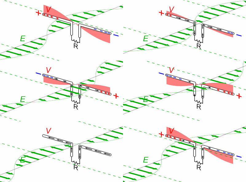
400px-Dipole_receiving_antenna_animation_6_800x394x150ms.gif
 
Also Gunner: Remember BOTH lengths of the Dipole must be Equal!
So each side/length should be about 102 inches long +/-...When tuning if you trim an inch off the Top ...you must trim the bottom same length...both ends need to be equal!

Also when you strip the coax to make your connections...the center and shield connection need to be same length also. And that striped length will ADD to the overall measurement!
 

dxChat
Help Users
  • No one is chatting at the moment.