
You are using an out of date browser. It may not display this or other websites correctly.
You should upgrade or use an alternative browser.
You should upgrade or use an alternative browser.
-
You can now help support WorldwideDX when you shop on Amazon at no additional cost to you! Simply follow this Shop on Amazon link first and a portion of any purchase is sent to WorldwideDX to help with site costs.
-
A Winner has been chosen for the 2026 July 4th Retevis RA89R Giveaway! Click Here to see who won!
Kenrich Eagle 500-Next Patient
- Thread starter Dmans
- Start date
Divertx,
Attached is the copy of the Eagle 500 schematic I have. It is not a very good copy but is mostly readable. I'm not sure how different this schematic may be from your 515 but you can compare components and may find you can use this 500 schematic.
Good Luck and welcome to the forum!
73
David
Attached is the copy of the Eagle 500 schematic I have. It is not a very good copy but is mostly readable. I'm not sure how different this schematic may be from your 515 but you can compare components and may find you can use this 500 schematic.
Good Luck and welcome to the forum!
73
David
Attachments

Hey was looking for the schematics for the kenrick eagle 525 amp 2 driving 5 20lf6 Raytheon tubs. Can I get a copy of the schematics? Please my email is dorr3931@gmail.com, Bug aka 654 Las Vegas, nevada
I have a eagle 400... I just replaces the 3 capacitors and fired up the amp .. the 2 6lf6 tubes lit up but the 5 20lf6 tubes did not... could this be because one tube is bad and they are in series... thanks any advice would be great
could this be because one tube is bad and they are in series...
Lacking a tube tester, check for continuity between pins 1 and 12 on each 20LF6. Easy to identify, those are the pins on opposite sides of the gap.
Consider for a moment that five 20-Volt heaters add up to 100 Volts. Your wall outlet delivers between 120 and 125, most likely. This runs the five final tubes a bit too hot. It was originally designed to use a 27LF6 tube in the five final sockets, but those are mostly unobtanium. Adding a 25 to 30 ohm 30 or 50 Watt resistor in series with those five heaters will drop the additional 20 Volts to keep the five final tubes' heaters at a safe voltage.
Here's how we do it:
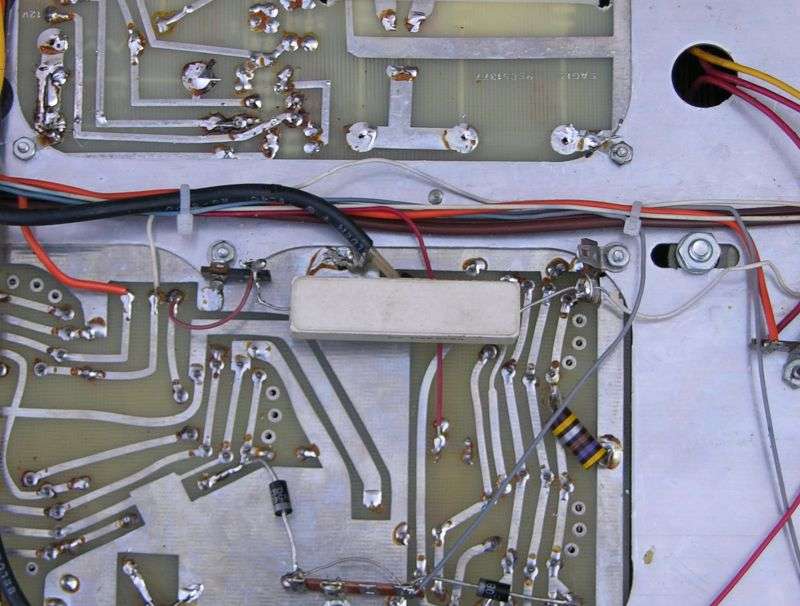
Makes me wonder if we should make a kit of that resistor, two tie strips and a piece of wire.
Probably not today.
73
Thank you to the op. This will be much help adding the refurb kit to my eagle 500. Thankfully my eagle has been very reliable so far it will swing 700 and if I can hear someone I can almost always make it back to them. The only issues mine has is that the preamp doesent work and the ssb delay is too long. Nevertheless I know that the elecrolytics are past life expectancy so a refurb is in order. also the only time I have cherried the tubes is driving it hard on ssb. I was able to score 6 matched tall 20lf6 tubes for les than 25 a peice so I hope to run this thing for a long time. Love my Oklhoma made box.
I would do whatever I could to knock down the filament voltage to 18-22 volts. I believe there is a post by @nomadradio addressing this in the thread. (Adding a resistor in series with the filament voltage wiring is the best way as 27LF6 tubes would be impossible to find now)I was able to score 6 matched tall 20lf6 tubes for les than 25 a peice
The owner of this particular Kenrich was not having any of this as I could not convince him that it would not reduce the output power of the amplifier.
This particular amplifier is probably in the junk pile now!

73
David
well maybe the previous owner did the filament mod, but I have not had a problem and have been running for about 4 months, sometimes on standby several hours a day. I will do the mod when I open it up for the recap.I would do whatever I could to knock down the filament voltage to 18-22 volts. I believe there is a post by @nomadradio addressing this in the thread. (Adding a resistor in series with the filament voltage wiring is the best way as 27LF6 tubes would be impossible to find now)
The owner of this particular Kenrich was not having any of this as I could not convince him that it would not reduce the output power of the amplifier.
This particular amplifier is probably in the junk pile now!
73
David
What about a 20 volt filament transformer is there such a thing?
A separate filament transformer is one way to do it. Each 20LF6 draws .6a filament current. Six of them would need 4.2a from the transformer minimum- 5.0a would be better.
Fitting another transformer into that chassis would be much more trouble than adding a 25-30w resistor on the underside of the chassis.
73
David
Fitting another transformer into that chassis would be much more trouble than adding a 25-30w resistor on the underside of the chassis.
73
David
Well the eagle uses 2 20lf6 driving 5 20lf6, so does the resister mod regulate the filament voltage for the 2 driver tubes or should I add something like this transforme? https://www.ebay.com/itm/MagneTek-F...d=link&campid=5336136228&toolid=20001&mkevt=1A separate filament transformer is one way to do it. Each 20LF6 draws .6a filament current. Six of them would need 4.2a from the transformer minimum- 5.0a would be better.
Fitting another transformer into that chassis would be much more trouble than adding a 25-30w resistor on the underside of the chassis.
73
David
On the schematic it's the five finals, V-3 thru V-7 that run off of the line voltage, the two drivers V- 1&2 have a tap off the transformer for the filaments.
73
Jeff
73
Jeff
The transformer you linked would be sufficient for the filament voltage of the 2 driver tubes( @ .6a per tube, the 2 amp secondary is more than enough headroom).
As you can see from the schematic (attached), the driver filament voltage comes from a secondary of the main transformer. If I remember correctly, during the refurb of this Kenrich 500 (subject of this thread) the filament voltage on the 2 driver tubes was 32 volts during standby and 27 or 28 volts when keyed. A little "Hot" for a 20v filament tube.
The final tubes filaments are powered in series from the line voltage. The line voltage in my shop right now is 122Vac. Five 20LF6 tubes on that line voltage would be supplying 24.4V to each tube filament. Closer to the "rated" 20v the tube was designed for and would more than likely drop when keyed to transmit in the amplifier. (I'm pretty sure I measured the final filament voltage when keyed but do not have notes on the exact voltage.)
Your line voltage may be more or less than my measured line voltage at any time. And the voltage drop when keyed to transmit would also cause a voltage drop for the 2 driver tubes powered from the main transformer secondary.
I normally would not be concerned if the filament voltage varied + or - 10% of the rating.
Anything you could do to get the filament voltage on the 2 driver tubes to 20V (+/- 10%) would greatly extend the life of these extinct tubes.
It just seems to me a resistor inline with the filament feed is much simpler than an added transformer-but it is your amplifier.
73
David
Attachments
Just make sure you use 30KD6 tubes in the two driver sockets.
Or 27LF6, but those are incredibly scarce.
73
Or 27LF6, but those are incredibly scarce.
73
Ken passed September 5, 1998I wonder if kenny is still alive I so I would like to talk to him and see if he remembers me . That was a fun place to work.
Heart attack (Seems that the Wellers got the best of him)
dxChat
- No one is chatting at the moment.
