Hi all,
Got a question on the best, but most affordable RF sampler to use.
I've been using the below RF Sampler for quite some time now.

It's made in Russia, and below is a description of it:
"
DESCRIPTION:
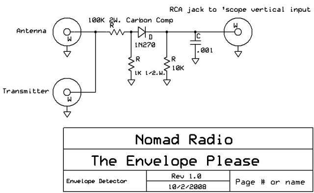
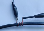
An RF sampling port, based on a toroid transformer design, designed to provide a safe sampling voltage of applied RF, so you can 'see' your modulation live on an oscilloscope connected to the sampled BNC port.
RF energy is sensed by the toroid secondary and provides a 30db reduction of the original signal up to 50 MHz at the BNC sampling port. The sampler can also be used at VHF and UHF frequencies, with a reduced sampled output.
Correctly terminated at 50 Ohms, so you don't need to provide external termination.
Two SO-239 pass-thru sockets provide a SWR neutral (1:1) path for your RF, the sampled energy is available at the BNC.
Insertion loss measured at 14.200 MHz was determined at -0.12db (in other words, no insertion loss).
At 100% duty cycle the sampler can handle 1000 Watts of continuous power, with a peak output max. of 1500 Watts, not to exceed 5 minutes duration with 15 minute gaps at this power level."
The question I have is,
Is there a better Sampler out there that will produce a cleaner signal on my Agilent 4411B spectrum analyzer and Oscope?
Reason I ask, is because I always have artifacts present in the signals and waveforms. I normally just adjust the RF stage until the artifacts get as low as I can get them, and leave it alone.
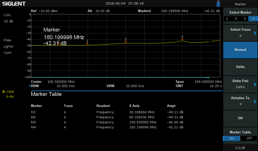
I have my spectrum analyzer set for 0dbm attenuation and a reference level of -10dbm, sweep set at 200ms, VBM and RBW set to automatic. The spectrum analyzer has a 50ohm input C-connector, which I use a C-connector to BNC adapter hooked to it which I then connect 6ft of 50hm coax with bnc connectors to.
The spectrum always has shorter signals on:
NOTE:
Short means 53dbm lower than the fundamental.
Tall means 48dbm lower than the fundamental.
Shorter means 54dbm lower than the fundamental.
Example radio Fundamental is: 27.205mhz @ 1.54dbm.
Approximate, not dead on the money on the below numbers:
32.55mhz (short)
33.055mhz (tall)
36.955mhz (shorter)
38.905mhz (shorter)
22.330mhz (short)
21.355mhz (tall)
17.530mhz (shorter)
15.500mhz (shorter)
My digital scope has a 1m ohm bnc connector on it, which I hook my 6ft 50 ohm coax with bnc to.
The waveform has short copies of artifacts of the large waveform in between each rise and fall of the waveform.
Could the Sampler I'm using be causing these artifacts? I do tune as much as I can to remove all other spikes while maintaining the fundamental spike, but I'm always left with just these, on about every radio I do.
I've had a few radios I did that cleaned up with no spikes at all, just the fundamental, with a flat noise floor throughout the rest of the frequency span.
Could cheap Chinese filtering caps (DC input 1000uf 25v) and regulator cap (1000uf 25v) be presenting these artifacts? I normally swap out those caps, but not on every radio. Only if it's an older radio. What could I do to remove those spikes? Certain electrolytic cap replacements recommended?
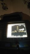
Included is a pic of what I mean. This pic is at a span of 30mhz. Sorry for it being inverted, but my rear camera on my phone doesn't work, so I have to turn phone around to take photos.
Got a question on the best, but most affordable RF sampler to use.
I've been using the below RF Sampler for quite some time now.
RF Sampler Modulation monitor 1-50 MHz (SSB, CW, AM, FM, Data) | eBay
Find many great new & used options and get the best deals for RF Sampler Modulation monitor 1-50 MHz (SSB, CW, AM, FM, Data) at the best online prices at eBay! Free shipping for many products!
www.ebay.com
It's made in Russia, and below is a description of it:
"
DESCRIPTION:
An RF sampling port, based on a toroid transformer design, designed to provide a safe sampling voltage of applied RF, so you can 'see' your modulation live on an oscilloscope connected to the sampled BNC port.
RF energy is sensed by the toroid secondary and provides a 30db reduction of the original signal up to 50 MHz at the BNC sampling port. The sampler can also be used at VHF and UHF frequencies, with a reduced sampled output.
Correctly terminated at 50 Ohms, so you don't need to provide external termination.
Two SO-239 pass-thru sockets provide a SWR neutral (1:1) path for your RF, the sampled energy is available at the BNC.
Insertion loss measured at 14.200 MHz was determined at -0.12db (in other words, no insertion loss).
At 100% duty cycle the sampler can handle 1000 Watts of continuous power, with a peak output max. of 1500 Watts, not to exceed 5 minutes duration with 15 minute gaps at this power level."
The question I have is,
Is there a better Sampler out there that will produce a cleaner signal on my Agilent 4411B spectrum analyzer and Oscope?
Reason I ask, is because I always have artifacts present in the signals and waveforms. I normally just adjust the RF stage until the artifacts get as low as I can get them, and leave it alone.
I have my spectrum analyzer set for 0dbm attenuation and a reference level of -10dbm, sweep set at 200ms, VBM and RBW set to automatic. The spectrum analyzer has a 50ohm input C-connector, which I use a C-connector to BNC adapter hooked to it which I then connect 6ft of 50hm coax with bnc connectors to.
The spectrum always has shorter signals on:
NOTE:
Short means 53dbm lower than the fundamental.
Tall means 48dbm lower than the fundamental.
Shorter means 54dbm lower than the fundamental.
Example radio Fundamental is: 27.205mhz @ 1.54dbm.
Approximate, not dead on the money on the below numbers:
32.55mhz (short)
33.055mhz (tall)
36.955mhz (shorter)
38.905mhz (shorter)
22.330mhz (short)
21.355mhz (tall)
17.530mhz (shorter)
15.500mhz (shorter)
My digital scope has a 1m ohm bnc connector on it, which I hook my 6ft 50 ohm coax with bnc to.
The waveform has short copies of artifacts of the large waveform in between each rise and fall of the waveform.
Could the Sampler I'm using be causing these artifacts? I do tune as much as I can to remove all other spikes while maintaining the fundamental spike, but I'm always left with just these, on about every radio I do.
I've had a few radios I did that cleaned up with no spikes at all, just the fundamental, with a flat noise floor throughout the rest of the frequency span.
Could cheap Chinese filtering caps (DC input 1000uf 25v) and regulator cap (1000uf 25v) be presenting these artifacts? I normally swap out those caps, but not on every radio. Only if it's an older radio. What could I do to remove those spikes? Certain electrolytic cap replacements recommended?
Included is a pic of what I mean. This pic is at a span of 30mhz. Sorry for it being inverted, but my rear camera on my phone doesn't work, so I have to turn phone around to take photos.
Attachments
Last edited: