• You can now help support WorldwideDX when you shop on Amazon at no additional cost to you! Simply follow this Shop on Amazon link first and a portion of any purchase is sent to WorldwideDX to help with site costs.

Tram D201 40yr/100 Mile Restoration Done Right

Wildcat444

Yea, that's right.
Oct 16, 2009
8
4
13
Hi, I am restoring an old Tram D201 (23 ch with PC boards from late 1976) that I picked up, and want to do it right. I have scoured internet forums and sites, posted questions, and found it quite a task to gather what is needed to tackle this, but I am having fun!

RESISTORS & CAPACITORS:
-----------------------
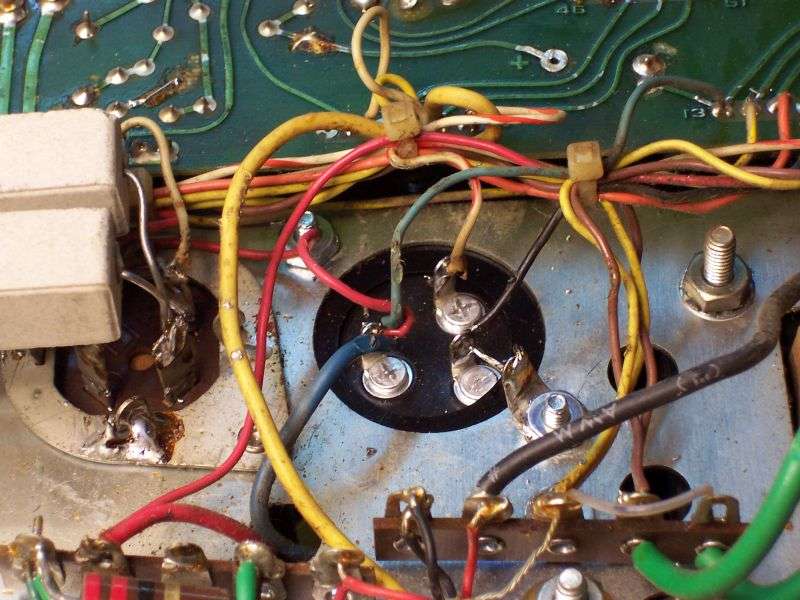
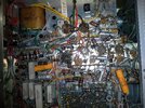
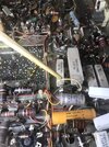
* As suggested, I will start by replacing all high wattage resistors, and upgrading the 1w to 2, the 2w to 3, the 3w to 4, the 7w to 10, and the 15w (all I could find were two 10w to either put in series or parallel depending on the value used) for a total of 20w.

* I will also start with replacing all electrolytics and the two line filter caps. I am confident in my selection of 50uf and 100uf 500v caps to replace the multi-section caps. I am also confident in my selection of two .0047uF X1Y2 safety caps from line to ground, and a .1uF X2 rated cap across the lines.

But what about the rest of the electrolytic caps... what voltages should the 16v, 150v, 250v, etc. be increased to if any? Should any of the capacitance values be changed? How about the wattage of the hi wattage resistors... is increasing to the next higher wattage enough for all positions?

Thanks!!
 

Here is a list. This is from 2600 about 15 years ago. I hope he doesn't mind me posting this. I blacked out some of my scribbling. It's for the 40 channel model but 95% will pertain to the 23 channel.
 

Attachments

  • D201A 100,000 mile tune up.png
    D201A 100,000 mile tune up.png
    7.3 MB · Views: 80
  • D201A 100,000 mile tune up pg2 .jpg
    D201A 100,000 mile tune up pg2 .jpg
    4.4 MB · Views: 63
  • Like
Reactions: Enterprise312ok
Here is another copy of the same that may be easier to read.
 

Attachments

  • TramTuneupPage1.pdf
    297.3 KB · Views: 61
  • TramTuneupPage2.pdf
    131.3 KB · Views: 45
Here is another copy of the same that may be easier to read.

Wow Tramd, this is an excellent list... very helpful. Thank you!

Next, I am ready to order replacement electrolytic capacitors... so I am wondering what voltages of radial and axial electrolytic capacitors (aside from the multi-section which I already have sorted out) that those experienced in these restorations are using? Is it recommended to upgrade for example, the 1uf from 50v to 450v or is that overkill? I seem to have problems finding some of these values in high voltages or that will physically fit from Mouser.
 
You can find the info in the parts section of the manual in case they may not be the original caps. There is no reason to use caps of extreme voltage value in circuits that are never going to see that kind of voltage. Most circuits in a radio do not run at the B+ voltage otherwise they would all have to be rated at 450v. 500v ones for the multi section can caps and 450v for C625 on the BA board to make the fuse do it's job are good to use. The 50v value for the 1uf is the most common voltage you will see for that particular cap but most others will have different voltages available. It doesn't hurt to use a slightly higher voltage cap such as a 25v in place of a 16v but don't get carried away. Remember the radio has run this way just fine all these years with the stock values. It's just time to replace them. Kinda like replacing spark plugs in your car. They just wore out.
 
The two-section 100uf 500-Volt filter is available from Parts Express.

https://www.parts-express.com/parts...trolytic-multi-section-can-capacitor--020-608

Needs a mount clamp.

https://www.parts-express.com/139-m...high-voltage-electrolytic-capacitors--020-615

Good news is that the hole spacing to mount the clamp matches the rivets in the old metal saddle that holds the old twist-lock filter. You'll have to drill out the rivets, and provide a ground lug under one of the two screws that mount the new clamp.

Here's what it looks like done this way.

HlAEir.jpg


73
I need this pic for the hand wired if someone has it or a link. Mike on you tube get close, but this quality is what I am looking to get. Thank you!
 
How's this?
That's the ticket! I installed CE multi caps. Just like the original have a triangle, square, and D symbol. Not, JJ , they only have three solder 2+ and one - I think. I could not find the instructions or good pic on how to wire them.
 
Last edited:
That's the ticket! I installed CE multi caps. Just like the original have a triangle, square, and D symbol. Not, JJ , they only have three solder 2+ and one - I think. I could not find the instructions or good pic on how to wire them.
If you use the schematics it will give all you need to know. The cap is in sections that usually have different values of capacitance but in the Tram version, I believe if memory serves me well these are all rated at 40uf @ 450 VDC and that value is specific to the circuits shown on the power supply side of the schematic. Just follow the yellow brick road. I just remembered that one of these caps is 10uf taps don't know which one you are dealing with but the answer is still the same.
 
  • Like
Reactions: bucketofguts
I need a large copy of the schematics. The JJ caps are 50/50 500 and 100/100 500. You ate right Tram uses 10/10/10/10 450, 40/40/40/ 450 if I am not mistaken.
 
The 3-section 40-40-40 is wired as a two-section cap. Two of the three are wired in parallel. This makes it a 80+40uf part. The two-section 100uf part replaces it just fine. That's what we have been using for about 25 years. The "LCR" brand we were buying back then is more expensive than the JJ parts we use now. Had quality issues with some LCR caps about 20 years ago, never went back to them. The additional capacitance on the side that was originally only 40uf doesn't seem to make a difference in performance. If it does, it can't be much.

73
 
  • Like
Reactions: bucketofguts

dxChat
Help Users
  • No one is chatting at the moment.
  • @ Wildcat27:
    Hello I have a old school 2950 receives great on all modes and transmits great on AM but no transmit on SSB. Does anyone have any idea?
  • @ ButtFuzz:
    Good evening from Sunny Salem! What’s shaking?
  • dxBot:
    63Sprint has left the room.
  • dxBot:
    kennyjames 0151 has left the room.